
Operation Manual
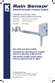

INSTALLATION: 3208-HRFS/3208-HRS
WIRING Models 3208-HRFS (Rain Freeze Sensor) or 3208-HRS (Rain Sensor)
IMPORTANT: The rain sensor is designed for 24-VAC irrigation controllers only. All wiring must
conform to applicable local building codes and regulations. K-Rain Rain Sensors will not work
with open circuit timers.
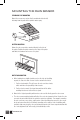
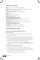
1. Installing the wired rain sensor on Sensor Terminals, simply:
• Find the controller sensor terminals
(generally marked “SENSOR”, “SEN” or “S”)
and attach the Rain Sensor control wires
directly to these terminals in any order.
NOTE:
1. There may be a jumper tab or wire between the sensor terminals that must be removed.
2. If a rain sensor will not be installed, the preinstalled jumper wire must remain installed
on the SENSOR terminals.
3. The manual activation cycle of some controllers bypasses the sensor inputs.
The controller must be in Automatic mode in order for the sensor to work properly.
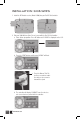
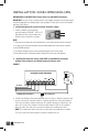
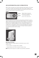
2. Installing the wired rain sensors 3208-HRFS or 3208-HRS into controllers
without sensor terminals and without pump start/master valve:
FIGURE 1
A. 24-VAC Solenoid Valves Only (No Pump Start Relay See Figure 1). With the two wires from
the rain sensor at the controller, locate the “common ground” wire of the solenoid valves.
If it is connected to the common terminal on the controller disconnect it. Attach one wire
of the rain sensor to the “common” terminal (usually marked “COM”) on the controller.
Attach the other wire of the rain sensor to the common wire leading to the valves.
NOTE: The common wire to the valves does not have to be interrupted at the controller.
The rain sensor may be wired anywhere along the common wire line.
1234
COM
Irrigation System Controller
Wire ConnectorCommon Wire from Valves
To Valves
24 VAC
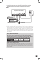
1234
COM
PUMP/
MV
Irrigation System Controller
Pump Start Relay/
Master Valve
Wire ConnectorCommon Wire from Valves
To Valves
24 VAC
05
www.krain.com