
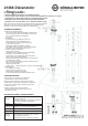
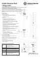
Technical data


USAGE NOTES / FUNCTION
CHECK, MAINTENANCE, CLEANING
MOVING THE WEIGHT
- Careful use of the distance rod maintains the use of
- the telescope and the load bearing functionality of
- the installation
- Perform workstation maintenance only without the
- subwoofer, loudspeaker and satellite box on the rod
- and watch for eventual risks (pinched fingers, impact,
- the rod falls over)
- To care for the product use a damp cloth and a non-
- abrasive cleaning agent
FAULT FINDING (F) and SOLUTION (S)
F: Installation is not stable:
F: S: Ensure that the surface is even.
F: S: Tighten the mandrel's locking rings 7
F: S: and the clamping screws 14.
F: Distance rod is not stable / retracts:
F: S: Tighten the clamping screw 14
F: S: Check locking pin 13 to see if it clicked into place
F: Loudspeaker sways back and forth on the locking pin
F: S: Tighten locking ring 7
F: S: Check loudspeaker connector (max. ø 36 mm)
F: S: US loudspeaker connectors (ø 38)
F: S: always use adapter sleeve 21326
F: It is difficult to turn the loudspeaker
F: S: Pick up the loudspeaker a bit when turning
F: S: the loud speaker
F: S: Loosen the locking pin 5 somewhat
NOTE!
Do not underestimate the weight of the loudspeaker
- placement and distance of the loudspeaker must be carried out
- by physically fit technicians,
- firmly grasp the distance rod when adjusting the height and locking in
- the locking pin.
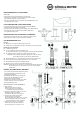
ATTACH LOUDSPEAKER TO THE STAND
5 Turn the Mandrel Locking Ring to the right (Direction OPEN),
5 to be able to set the system to the smallest diameter.
6 Place the loudspeaker on the rod (directly or with a K&M-Adapter).
7 Now turn the locking ring to the left (Direction CLOSE) until the
7 mandrels lock into place.
CHANGE THE DIRECTION OF THE LOUDSPEAKERS
Open locking ring 5 and turn the loudspeaker in the desired direction.
Tighten locking ring 7 (Direction CLOSE).
Technicians:
FP - First Person: operates the distance rod with the weight
SP - Second Person: operates the clamping bracket's clamping screw and locking pin
Order when extending the rod:
FP -
18 holds the distance rod
SP - 19 loosens the clamp screw and holds it
SP - 10 pulls the locking knob until the locking pin is no longer in the locked position
FP - 11 extends the distance rod with the box to the desired approx. height;
EP - 11 NOTE: to find the pin hole easily, the locking pin
EP - 11 NOTE: should be placed just above the hole
SP - 12 lets go of the locking knob, so that the pin can click into the distance rod
FP - 13 slowly lowers the distance rod so that the locking pin locks into the hole
SP - 14 tightens the clamping screw (manual strength is enough)
When retracting the distance rod the reverse order applies.
IMPORTANT: ensure that one person tightens the clamping screw 14 immediately
IMPORTANT: in the event the second person is not able to hold the distance rod.