
Installation Manual
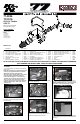

INSTALLATION INSTRUCTIONS
Continued
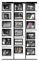
10. Install the heat shield mounting bracket (07190)
onto the heat shield using the provided spacer and
hardware.
11. Install the heat shield mounting bracket
(070902) onto the heat shield using the provided
spacers and hardware.
12. Install the lter adapter onto the heat shield and
secure with the provided hardware.
13. Install the provided edge trim onto the heat
shield as shown.
NOTE: Some trimming of the edge trim will be
necessary.
14. Set the heat shield into the engine
compartment and secure the factory install nuts
with the provided hardware.
NOTE: Be sure to place the ground strap
between the mounting bracket and the inner
fender, then secure with the heat shield
mounting bolt.
15. Install the silicone hose (08497) onto the
throttle body and secure with the provided hose
clamp.
16. Install the silicone hump hose (08418) onto the
lter adapter and secure with the provided hose
clamp.
17. Remove the two screws securing the mass
air sensor. Remove the mass air sensor from the
upper air box housing.
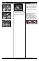
18. Install the mass air sensor into the intake tube
and secure with the provided hardware.
19. Install the provided NPT vent ttings into the
K&N
®
intake tube as shown.
NOTE: Plastic NPT ttings are easy to cross
thread. Install the vent tting “hand” tight, then
turn it two complete turns with a wrench.
20. Install the hose mender into the provided crank
case vent hose as shown.
21. Install the crank case vent hose assembly into
the factory crank case vent hose as shown.
22. Install the K&N
®
intake tube into the hump hose
attached to the heat shield and then into the step
hose attached to the throttle body. Secure with the
provided hose clamps.
23. Connect the crank case vent hose and the fuel
pressure hose to the ttings connected to the K&N
®
intake tube.
24. Install the K&N
®
air lter and secure with the
provided hose clamp.
NOTE: Drycharger
®
air lter wrap; part #
RF-1020DK is available to purchase separately.
To learn more about Drycharger
®
lter wraps or
look up color availability please visit
http://www.knlters.com
®
.
25. Reconnect the mass air sensor electrical
connection.
26. Remove the front engine cover mounting stud
from the intake manifold.
27. Install the provided stud into the mounting stud
location as shown.