
Installation Manual
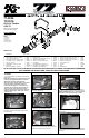

77-9036
TOOLS NEEDED:
NOTE: FAILURE TO FOLLOW INSTALLATION INSTRUCTIONS AND NOT USING THE PROVIDED HARDWARE
MAY DAMAGE THE INTAKE TUBE, THROTTLE BODY AND ENGINE.
PARTS LIST:
Description Qty. Part #
NOTE: This kit was not designed
to t vehicles with a body lift.
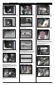
1. Turn off the ignition and disconnect the negative
battery cable.
NOTE: Disconnecting the negative battery cable
erases pre-programmed electronic memories.
Write down all memory settings before
disconnecting the negative battery cable. Some
radios will require an anti-theft code to be
entered after the battery is reconnected. The
anti-theft code is typically supplied with your
owner’s manual. In the event your vehicles’
anti-theft code cannot be recovered, contact an
authorized dealership to obtain your vehicles
anti-theft code.
TO START:
3. Lift off the engine cover.
2. Disconnect the mass air sensor electrical
connection and then unhook the wiring harness
from the air box.
4. Loosen the hose clamp that secures the intake
tube to the throttle body.
5. Disconnect the crank case vent hose and fuel
pressure line from the intake resonator.
6. Release the four retaining clips securing the
upper air box, then remove the upper air box and
intake tube assembly from the vehicle.
7. Loosen the two bolts securing the lower air box,
and then remove the lower air box from the vehicle.
NOTE: K&N Engineering, Inc., recommends that
customers do not discard factory air intake.
8. Remove the bolt securing the ground strap to the
inner fender.
9. Install the heat shield mounting bracket (070742)
onto the heat shield using the provided spacer and
hardware.
TOYOTA
2012-14 Tundra
V8-5.7L
Flat Blade Screwdriver
Phillips Screwdriver
Ratchet
Extension
10mm Socket
9/16 Wrench
10mm Wrench
3mm Allen Wrench
4mm Allen Wrench
A Hose Clamp # 56 1 08620
B Hose; 4” ID To 3.5” ID X 3” L TPRD 1 08497
C Hose Clamp # 64 Stainless 3 08645
D Vent; STRT, 1/8 Hose, 1/4 NPT, Plastic 1 08052
E Vent; STRT 1/2” Hose, 1/4”NPT, Plas 1 080022
F Hose; 1/2” ID X 7”L 1 08159
G Hose Mender; 1/2” Barbed, Nylon 1 08686
H Intake Tube 1 27549KP
I Bolt; M4-0.07 8MM, A/H Cap, SS 2 07733
J Hose; 4” ID X 3” L Hump Reinforced 1 08418
K Edge Trim (75”) 1 102460
L Bolt; M6 X 1.00 X 16MM, ButnHd. SS 2 07730
M Washer; M6 Split Lock Zinc 5 1-3025
N Washer; 1/4” ID X 5/8” OD -SAE 13 08275
O Heat Shield 1 074107
P Nut; 6MM Nylock, Hexhead, SS 4 07512
Q Bolt; M6 X 1.00” X 20MM Hex, SS 4 07795
R Bolt; 6MM-1.00 X 16MM, SS 3 07812
S Bracket; 57-3017, “L,” Fin, TB/PC 1 070742
T Spacer; .625” OD X .250” ID X .250” L 4 06555
U Bracket; 63-1088, Mild STL, TB/PC 1 07190
V Bracket; 57-1513, L-Bend, Fin, TB/PC 1 070902
W Adaptor; 57-3058 #454 1 27300
X Hose Clamp # 104 1 08697
Y Air Filter 1 RF-1044
Z Stud 1 1-107
AA Nut Extension 1 08254
Y
X
W
Q
N
N
N
N
N
K
C
C
H
AA
I
D
C
B
A
F
G
E
J
M
M
L
L
P
V
N
M
T
T
R
Q
S
N
N
N
M
R
Q
T
P
O
N
T
N
Q
M
N
U
R
P
Z