
Installation Manual
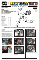

INSTALLATION INSTRUCTIONS
Continued
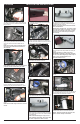
12. Remove the stock intake tube as shown.
NOTE: K&N Engineering, Inc., recommends that
customers do not discard factory air intake.
13. Secure the provided rubber mounted stud
to the air inlet ange on the lower air cleaner
assembly using the provided hardware as shown.
14. Remove the two stock bolts on the bulkhead as
shown.
NOTE: Some models may contain two, T30 Torx
screws.
15. Install the provided edge trim onto the K&N
®
heat shield as shown.
16. Install the heat shield onto the top edge of
the lower air cleaner assembly, then, secure the
front tab of the heat shield to the lower air cleaner
assembly using the provided screw as shown.
17. Using the two screws from step 14, secure the
heat shield to the bulkhead as shown.
18. Tighten all hardware on the heat shield as
shown.
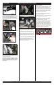
19. Install the silicone hose and the provided hose
clamp onto the throttle body and tighten as shown.
20. Secure the provided “Z” bracket onto the
threaded boss on the K&N
®
intake tube using the
provided hardware as shown.
NOTE: The slotted end of the bracket is bolted
to the threaded boss.
NOTE: Before installing the “Z” bracket, inspect
the inside of the tube for any debris, then clean
the inside out with water and a towel. Inspect
the tube one more time before proceeding to
the next step.
21. Install the K&N
®
air lter onto the K&N
®
intake
tube and tighten with the provided hose clamp as
shown.
NOTE: Drycharger
®
air lter wrap; part #
RX-4990DK is available to purchase separately.
To learn more about Drycharger
®
lter wraps or
look up color availability please visit
http://www.knlters.com
®
.
22. Install the hose clamp onto the silicone hose as
shown.
23. Install the intake tube assembly into the silicone
hose at the throttle body, then, line up the bracket
with the rubber mounted stud as shown.
24. Using the provided hardware secure the “Z”
bracket to the rubber mounted stud as shown.
NOTE: Adjust for best t and clearance, then,
tighten all hose clamps and hardware.
19a. On vehicles that come equipped with the
additional vent line, install the provided vent tting
into the intake tube as shown. On all others install
the provided plug.
NOTE: Plastic NPT ttings are easy to cross
thread. Install the vent tting “hand” tight, then
turn it two complete turns with a wrench.
11. Pull upward on the stock intake tube, then,
using a pair of pliers disconnect the stock crank
case vent hose from the stock intake tube as
shown.
NOTE: Some models may be equipped with a
second vent line, which will also need to be
disconnected.
10. Using a pair of dikes or pliers, unclip the stock
hose clamp on the stock intake tube at the throttle
body as shown.