
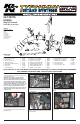
Installation Manual

• 1455 CITRUS ST., P.O. BOX 1329, RIVERSIDE, CA., U.S.A. 92502 • TECH SERVICE 800-858-3333 • FAX 951-826-4001
• e-mail: tech@knlters.com
®
• WWW: http://www.knlters.com
®
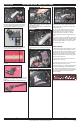
ROAD TESTING:
1. Start the engine with the transmission in neutral
or park, and the parking brake engaged. Listen for
air leaks or odd noises. For air leaks secure hoses
and connections. For odd noises, nd cause and
repair before proceeding. This kit will function iden-
tically to the factory system except for being louder
and much more responsive.
2. Test drive the vehicle. Listen for odd noises or
rattles and x as necessary.
3. If road test is ne, you can now enjoy the added
power and performance from your kit.
4. K&N Engineering, Inc., suggests checking the air
lter element periodically for excessive dirt build-
up. When the element becomes covered in dirt (or
once a year), service it according to the instructions
on the Recharger
®
service kit, part number 99-
5050 or 99-5000.
33. It will be necessary for all K&N
®
high ow intake
systems to be checked periodically for realignment,
clearance and tightening of all connections. Failure
to follow the above instructions or proper mainte-
nance may void warranty.
31. Reconnect the vehicle's negative battery cable.
Check to ensure all hose clamps and ttings are
properly tightened and positioned correctly before
starting the vehicle.
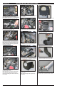
25. Insert the hose mender into the crank case vent
chamber. Secure using the stock clamp removed in
step # 3.
NOTE: Insert the end cut in the previous step.
26. Install the provided silicone hose onto the hose
mender as shown.
27. Install the crankcase chamber assembly onto
the K&N
®
intake tube and valve cover. Secure with
the provided hose clamp.
NOTE: Some trimming of the ½” silicone hose
may be necessary.
28. Install the stock vent hose onto the K&N
®
in-
take tube as shown. Secure with the provided hose
clamp.
29. Install the K&N
®
air lter onto the intake tube
as shown.
30. Re-connect the mass air sensor connector as
shown.
23. Install the provided silicone hose (#084074)
onto the stock crankcase vent chamber. Secure
with the provided hose clamps as shown.
24. Cut two barbs off of the provided hose mender
as shown.
18553D
9/05/14
INSTALLATION INSTRUCTIONS
Continued
22. Install the K&N
®
intake tube into the silicone
hose at the throttle body and align with the tube
mounting bracket installed in step # 13. Secure
with the provided hardware and hose clamp.
32. The C.A.R.B. exemption sticker, (attached),
must be visible under the hood so that an emis-
sions inspector can see it when the vehicle is
required to be tested for emissions. California
requires testing every two years, other states may
vary.
* FREE K&N
®
decal To register your warranty, please see us online at knlters.com/register. FREE K&N
®
decal *