
Installation Manual
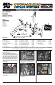

INSTALLATION INSTRUCTIONS
Continued
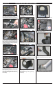
10. Remove the stock coolant hose assembly from
the vehicle.
11. Install the supplied coolant hose onto the ther-
mostat housing and throttle body. Secure with the
provided clamps as shown.
NOTE: Replace any coolant recovered during
hose removal by replenishing the recovery
tank. Some trimming of the coolant hose may
be necessary.
12. Install the provided silicone hose (#08440) onto
the throttle body. Secure with the provided hose
clamp as shown.
13. Install intake tube bracket (#06498) onto the
thermostat housing with the provided hardware as
shown.
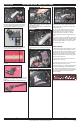
14. Remove the bolt securing the ground strap to
the frame rail.
NOTE: This bolt will be re-used.
15. Install angled “L” bracket (#06497) onto the
frame rail. Secure the “L” bracket and ground strap
using the bolt removed in step #14.
16. Install the provided edge trim onto the heat
shield as shown.
NOTE: Some trimming of the edge trim may
be necessary.
17. Install “L” bracket (#06499) onto the heat shield
with the provided hardware as shown.
18. Install the heat shield assembly with the
provided hardware as shown.
19. Remove the mass air sensor from the stock
airbox.
20. Depress the spring clamp and remove the
crankcase vent chamber from the stock intake
tube.
21. Install the mass air sensor into the K&N
®
intake tube with the provided hardware as shown.
8. Depress the spring clamp and remove the crank-
case vent hose from the valve cover.
9. Depress the spring clamps on the stock coolant
hose at the throttle body and thermostat housing.
NOTE: Ensure the engine is completely cool
before removing the coolant hose, or hot cool-
ant will escape from the cooling system and
cause injury or damage.
7. Unclip the wiring harness from the bottom of the
stock airbox and remove from the vehicle.
NOTE: K&N Engineering, Inc., recommends that
customers do not discard factory air intake.