
Owners manual


WIRING INSTALLATION
1. The following steps describe the proceedure
for the installation of the Wiring harness and
associated connections. Specic layouts may
vary on your application.
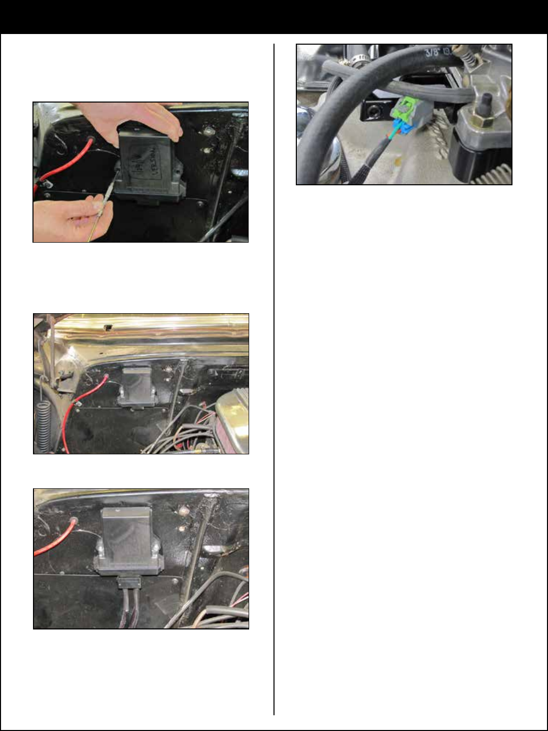
2. Find a suitable location to mount the ECI control
unit that is away from direct heat, wet conditions
and any mechanical interference. Place the control
unit in position and mark the location for holes to
be drilled.
3. Drill the holes and mount the control unit in the
desired location.
4. Connect the wiring harness to the control unit.
5. Route the wiring pigtails for the injector(s)
and other optional connections so they will not
interfere with mechanical assembly or exhaust and
then connect them to the injector(s) and optional
locations.
NOTE: See diagram on page 11, all of the wiring
pigtails and connectors are labeled.
6. The following electrical connections will need to
be made and routing will vary depending on your
application. (SEE CHART & DIAGRAM ON PAGES
10 & 11).
RPM signal
O2 sensor
12 volt ignition on
Ground
Injector(s)
OPTIONAL CONNECTIONS
AFR out
Temperature 1, 2 coolant temperature
MSD
®
tach adapter part# 8910
9