
Data Sheet

19688 Speaker mount for
JBL-Control 1
- Mount JBL-Control 1 to a floor stand
- for connection threads 3/8" and 5/8" (with the correct reducer)
- variable adjustments both for angle and direction
- Dimensions: W x D x H 53 x 105 x 132 mm, Weight: 0.5 kg
SAFETY NOTES
- NOTE: This mount is configured for the "JBL Pro - Control 1", the housing is equipped with
- the corresponding slots (Fig. a, b)
- "JBL Pro - Control 1 Pro", "JBL Home - Control ONE", "JBL Home - Control 1 Extreme" are
- NOT SUITABLE for this stand, because these are mounted using a female thread onto the
- back of the housing; Slots for the 19688 mount are missing.
- The stand must be able to securely hold the weight of the mount and the loud speakers; this
- applies to the weight bearing load and stand stability (the leg circumference must be properly
- sized)
- Please ensure that after the installation is completed that the adapter, loud speaker and stand
- screws are properly tightened and please check this routinely.
- Be sure that the stand surface will bear the load and is suitable and level.
- Only suitable for indoor use
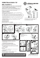
A Assemble the swivel arms - B1, B2, B3 Assemble the bracket - C Disassembly
Check the components; ensure that they are all there
and that the components are in functioning order:
1 Swivel pre-assembled - 2 Reducer thread 3/8-5/8" -
3 Bracket - 4 U-disk ø 6.4 mm - 5 Lock nut M6 - 6 Cap
SETUP INSTRUCTIONS
Connect mount with JBL-Control 1
D Check the connection thread of the stand: Is it 3/8" or 5/8"?
D If it is a 3/8" thread the reducer 2 is left in the joint:
D - ensure that it fits tightly
D If it is a 5/8" thread the reducer 2 is removed:
D - we recommend that the reducer is kept for future use.
E Screw the knurled washer onto the stand - as far as it will go.
F Screw the stand tube onto the female thread of the mount.
G Screw the knurled washer onto the mount so that the screw
G connection is tight routinely check that the counter nuts are tight.
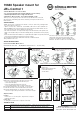
Mount Control 1 to the Stand
H ANGLE
H Hold Control 1 - loosen wing-nut 7 - adjust Control 1 angle 8 -
H tighten the wing-nut 7.
I DIRECTION
I To change the speaker direction, adjust the stand tube.
Adjust Control 1
- is performed in the reverse order.
- Please note:
- Remove the bracket from the
- U-arms with the help of
- a screw driver.
U-Arms 1 place hook into the
front slot on Control 1
Push the U-arm 1 and bracket 3
together until the pin
clicks into the hole
Screw the U-disk 4 and nut M6 5
together with the threaded bolt place
the cap 6 on the bolt
Check if Control 1 is securely mounted to the arms and the bracket.
A
Place into the box slit 3.a by placing the bracket 3
over the threaded bolt.
B1
B2 B3
C
D
E
KÖNIG & MEYER GmbH & Co. KG
Kiesweg 2, 97877 Wertheim, www.k-m.de
19688-300-55 Rev.07 03-80-128-00 4/14
Thank you for choosing this product. The instructions provide directions to all of the
important set up and handling steps. We recommend you keep these instructions for
future reference.
F H
G
I
TECHNICAL DATA
Material
Sheet metal mount: Steel, black powdered - Swivel: zinc die-cast, black powdered
Connecting elements: Steel, galvanized - Handle: PA / Cap: PE / Rubber disks
max. Load Loud speakers JBL Control 1, Pro Series (2.3 kg) - please refer to the SAFETY NOTES
Weight 0.5 kg