Electronic Preset Counter With two presets Models LCD positive LCD positive, green backlighting LCD negative, red backlighting LCD negative, red-green backlighting Compteur à présélection électronique deutsch Ausführungen LCD positiv LCD positiv, grün hinterleuchtet LCD negativ, rot hinterleuchtet LCD negativ, rot-grün hinterleuchtet english mit zwei Vorwahlen français Elektronischer Vorwahlzähler Exécutions LCD positif LCD positif, rétroéclairage vert LCD négatif, rétroéclairage rouge LCD négatif,
Inhaltsverzeichnis 1 2 3 4 5 6 7 Vorwort Sicherheits- und Warnhinweise 4 4 2.1 2.2 2.3 4 4 4 Bestimmungsgemäßer Gebrauch Schalttafeleinbau Elektrische Installation Beschreibung Anzeige/Bedienelemente Eingänge 5 5 5 5.1 5.2 5.3 5.4 5.5 5 5 5 5 5 INP A, INP B RESET GATE LOC.INP MPI Ausgänge 6 6.1 6.2 6.3 6 6 6 Ausgang 1 Ausgang 2 Aktive Ausgänge Programmierung 7.1 7.2 7.3 7.4 7.5 7.6 7.7 7.
11 Lieferumfang 12 Bestellschlüssel 13 Frequenzen (typ.) 14 15 16 17 18 18 18 18 18 19 19 19 20 13.1 Impulszähler 13.2 Frequenzzähler 20 20 Eingangsarten Impulszählung Eingangsarten Zeitmessung Eingangsarten Frequenzzähler Ausgangsoperationen Maßbilder 21 23 24 25 27 www.kuebler.com Seite 3 deutsch 10.9 Klimatische Bedingungen 10.10 EMV 10.11 Gerätesicherheit 10.12 Mechanische Daten 10.
1 Vorwort Lesen Sie vor der Montage und der Inbetriebnahme diese Bedienungsanleitung durch. Beachten Sie zu Ihrer eigenen Sicherheit und der Betriebssicherheit alle Warnungen und Hinweise. Wenn das Gerät nicht nach dieser Bedienungsanleitung benutzt wird, kann der vorgesehene Schutz beeinträchtigt werden. 2 Sicherheits- und Warnhinweise Benutzen Sie das Gerät nur in technisch einwandfreiem Zustand, bestimmungsgemäß, sicherheits- und gefahrenbewusst unter Beachtung dieser Bedienungsanleitung 2.1 2.
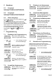
Beschreibung 6-stellige Multifunktions- LCD-Anzeige Gut ablesbare 2-zeilige LCD-Anzeige mit Symbolen für die angezeigte Vorwahl und den Zustand der beiden Ausgänge Gleichzeitige Anzeige des Istwert und der Vorwahlen bzw. den Nebenzählern Ausführung ohne/mit hintergrundbeleuchtetem Display Add./Subtr.
6.1 7.3 Ausgänge Mit der Prog/Mode-Taste wird das Untermenue geöffnet und der erste Menuepunkt wird angezeigt. Ausgang 1 Relais mit potentialfreiem Schließkontakt oder Optokoppler mit offenem Emitter und Kollektor 6.2 Ausgang 2 7.4 Relais mit potentialfreiem Wechselkontakt oder Optokoppler mit offenem Emitter und Kollektor. 6.3 7 7.
Ö 7.8 In der Anzeige wird für 2 s der Text SAVE angezeigt Programmiermenue 7.8.1 Voreingestellte Parametersätze Hinweis Es sind drei Parametersätze fest hinterlegt, die bei Bedarf angepasst werden können. Bei jedem Bestätigen der Parametersätze werden alle Parameter auf die in der Tabelle aufgeführten Werte zurückgesetzt. Der dEFAuL P.USEr kann frei programmiert werden. 7.8.2 Tabelle Parametersätze P.SEt 1 P.SEt 2 P.SET 3 Func Count Count Count InP.
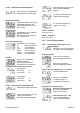
7.8.4 Impulszähler 7.8.4.1 Untermenue für die Signal- und Steuereingänge Menue zum Programmieren der Signal- und Steuereingänge Phasendiskriminator mit Impulsvervierfachung INP A: Zähleingang 0° INP B: Zähleingang 90° Jede Flanke von INP A und INP B wird gezählt.
Addierende Zählung mit automatischem Reset Ausgang 1 aktiv bei Zählerstand > Vorwahlwert 1 Ausgang 2 (Wischsignal) aktiv bei Zählerstand = Vorwahlwert 2 Automatischer Reset auf Null bei Zählerstand = Vorwahlwert 2 Reset auf Null Subtrahierende Zählung mit automatischem Reset Ausgang 1 aktiv bei Zählerstand < Vorwahlwert 1 Ausgang 2 (Wischsignal) aktiv bei Zählerstand = 0 Automatischer Reset auf Vorwahl 2 bei Zählerstand = 0 Reset auf Vorwahlwert 2 Addierende Zählung mit automatischem Reset und Batchzähler A
7.8.4.3 Untermenue zur Konfiguration Untermenue zur Anpassung der Eingangsimpulse und Anzeige keine Rückstellung möglich (rote Taste und Reset-Eingang gesperrt) nur elektrische Rückstellung möglich (Reset-Eingang) Multiplikationsfaktor Multiplikationsfaktor von 00.0001 bis 99.9999 einstellbar. Die Einstellung 00.0000 wird nicht übernommen Divisionsfaktor Divisionsfaktor von 01.0000 bis 99.9999 einstellbar. Die Einstellung < 01.
Frequenzmessung mit Richtungserkennung [Quad] Inp A: Frequenzeingang 0° Inp B: Frequenzeingang 90° Multiplikationsfaktor Multiplikationsfaktor von 00.0001 bis 99.9999 einstellbar. Die Einstellung 00.0000 wird nicht übernommen Divisionsfaktor Divisionsfaktor von 01.0000 bis 99.9999 einstellbar. Die Einstellung <01.
Anzeigefarbe obere Zeile untere Zeile rot grün 7.8.5.3 Vorwahl 1 weiter bei 7.8.6.5 7.8.5.4 Vorwahl 2 weiter bei 7.8.6.6 7.8.6 Zeitzähler 7.8.6.
7.8.6.
Schleppvorwahlbetrieb mit automatischem Reset Vorwahl1 wird bei Veränderung des Vorwahlwert 2 automatisch nachgezogen Automatischer Reset auf Null bei Hauptzähler = Vorwahlwert 2. Vorwahl 1 relativ zu Vorwahl 2 (siehe auch unter 17. Ausgangsoperationen) 7.8.6.3 Untermenue zur Konfiguration Parameter-Menue zum Anpassung der Zeitbereiche und Anzeige Anzeigefarbe obere Zeile untere Zeile rot grün 7.8.6.
add. Ausgangsoperationen: Wischsignal am Ausgang1, wird bei Zählerstand > Vorwahl 1 passiv. (Deaktivierung nur in positive Richtung) sub. Ausgangsoperationen: Wischsignal am Ausgang 1, wird bei Zählerstand < Vorwahl 1 passiv. (Deaktivierung nur in negativer Richtung). add. Ausgangsoperationen: Wischsignal am Ausgang1, wird bei positiver Richtung und Zählerstand > Vorwahl 1 aktiv und anschließend bei negativer Richtung und Zählerstand < Vorwahl 1 aktiv sub.
Zählerstand < Null passiv und anschließend bei positiver Richtung und Zählerstand > Null passiv 7.9.2 Einstellung mit Teach-Funktion MPI-Eingang auf tEAch programmieren Dauer des Wischsignals von Ausgang 2, einstellbar von 00.01 bis 99.99 s. Wischsignal wird nachgetriggert. Aktiv: Relais bzw. Optokoppler werden bei Erreichen des Vorwahlwerts angesteuert.
Anschlussbelegung 9.2.2 Ausführung mit Optokoppler Nr Benennung 9 Funktion Collector 1 Ausgang 1 10 Emitter1 deutsch 9 11 Emitter 2 Ausgang 2 12 nicht belegt 13 Collector 2 14 AC: 90..260 VAC N~ DC: 10..30 VDC Spannungsversorgung 15 AC: 90..260 VAC L~ DC: GND (0 VDC) Spannungsversorgung 10 Technische Daten 9.
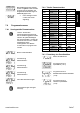
10.4 Zeitzähler Sekunden Minuten Stunden h.min.s 0.001 s ... 999 999 s 0.001 min ... 999 999 min 0.001 h .. 999 999 h 00h.00min.01s ... 99h.59min.59s kleinste messbare Zeit 500μs Messfehler < 50 ppm Ansprechzeit der Ausgänge: Relais < 7 ms Optokoppler < 1 ms 10.5 Signal- und Steuereingänge Polarität: programmierbar NPN/PNP für alle Eingänge gemeinsam Eingangswiderstand 5 k: Impulsform beliebig Schaltpegel bei AC-Versorgung: HTL-Pegel Low: 0 ... 4 VDC High: 12 ... 30 VDC 5V-Pegel Low: 0 ...
10.13 Anschlüsse deutsch Spannungsversorgung und Ausgänge: Steckbare Schraubklemme, 7-polig, RM5,08 Aderquerschnitt, max. 2,5 mm² Signal- und Steuereingänge: Steckbare Schraubklemme, 8-polig, RM 3,81 Aderquerschnitt, max. 1,5 mm² 11 Lieferumfang Vorwahlzähler Spannbügel Bedienungsanleitung 12 Bestellschlüssel 6.924.X1XX.XX0 Eingangspegel 0 = Standardpegel (HTL) A = 5V-Pegel Spannungsversorgung 0 = 90 .. 260 VAC 3 = 10 ..
13 Frequenzen (typ.) 13.2 13.1 HTL-Pegel AC-Versorgung Impulszähler HTL-Pegel AC-Versorgung DC-Versorgung 12V DC-Versorgung 24V Add Sub Trail typ.Low typ. High typ.Low typ. High typ.Low typ. High 2,5 V 22 V 2V 10 V 2,5 V 22 V AddAr SubAr AddBat SubBat TrailAr AddTot SubTot 2,8 kHz 2,7 kHz Up.Dn Up.Up 29 kHz 2,8 kHz 2,7 kHz Quad Quad 2 28 kHz 1,4 kHz 1,3 kHz Quad 4 18 kHz 1,2 kHz 0,9 kHz 5V-Pegel typ.Low typ.
Funktion Diagramm Hinweis: Wenn GATE-Eingang aktiv keine Zählung P = Preset (Vorwahlwert) PnP: Zählung bei steigender Flanke nPn: Zählung bei fallender Flanke Cnt.Dir Inp A: Zähleingang Inp B: Zählrichtung Add: Anzeige 0 --> Vorwahl Sub: Anzeige Vorwahl -> 0 Up.Dn Inp A: Zähleingang add Inp B: Zähleingang sub Add: Anzeige 0 --> Vorwahl Sub: Anzeige Vorwahl -> 0 Up.
Funktion Diagramm Hinweis: Wenn GATE-Eingang aktiv keine Zählung PnP: Zählung bei steigender Flanke nPn: Zählung bei fallender Flanke Quad 4 A 90° B Inp A: Zähleingang Zählung bei steigender und fallender Flanke Inp B: Zähleingang Zählung bei steigender und fallender Flanke, Umkehr der Richtung Add: Anzeige 0 --> Vorwahl Sub: Anzeige Vorwahl -> 0 A/B Inp A: Zähleingang 1 Inp B: Zähleingang 2 Formel: A/B (A-B)/A Inp A: Zähleingang 1 Inp B: Zähleingang 2 Formel: (A – B)/A x100 www.kuebler.
Funktion Diagramm InA.InB PnP: Zählung bei steigender Flanke nPn: Zählung bei fallender Flanke Inp A: Start Inp B: Stop Add: Anzeige 0 --> Vorwahl Sub: Anzeige Vorwahl -> 0 InB.
16 Eingangsarten Frequenzzähler Funktion Diagramm PnP: Zählung bei steigender Flanke nPn: Zählung bei fallender Flanke A Inp A: Frequenzeingang Inp B: ohne Funktion AsubB Inp A: Frequenzeingang 1 Inp B: Frequenzeingang 2 Formel: A-B AaddB Inp A: Frequenzeingang 1 Inp B: Frequenzeingang 2 Formel: A+B Quad A 90° B Inp A: Frequenzeingang 1 Inp B: Umkehr der Richtung A/B Inp A: Frequenzeingang 1 Inp B: Frequenzeingang 2 Formel: A/B (A-B)/A Inp A: Frequenzeingang 1 Inp B: Frequenzeingang 2 Formel:
17 Ausgangsoperationen Diagramm Nur im Mode Mode Zusätzlich im Mode und Add Sub AddAr SubAr AddBat SubBat AddTot SubTot www.kuebler.
Mode Diagramm Trail TrailAr www.kuebler.
deutsch 18 Maßbilder Fritz Kübler GmbH Zähl- und Sensortechnik P.O. Box 3440 D – 78023 Villingen-Schwenningen Germany Tel.: +49 (0) 77 20 – 39 03-0 Fax +49 (0) 77 20 – 2 15 64 sales@kuebler.com www.kuebler.com www.kuebler.
Electronic Preset Counter With two presets Models LCD positive LCD positive, green backlighting LCD negative, red backlighting LCD negative, red-green backlighting english CODIX 924
Table of Contents 1 2 3 4 5 6 7 Preface Safety Instructions and Warnings 4 4 2.1 2.2 2.3 4 4 4 Use according to the intended purpose Mounting in a control panel Electrical Installation Description Display/Operating elements Inputs 5 5 5 5.1 5.2 5.3 5.4 5.5 5 5 5 5 5 INP A, INP B RESET GATE LOCK INPUT MPI Outputs 6 6.1 6.2 6.3 6 6 6 Output 1 Output 2 Active Outputs Programming 7.1 7.2 7.3 7.4 7.5 7.6 7.7 7.
18 18 18 18 18 11 Scope of Delivery 12 Ordering codes 13 Frequencies (typical) 19 19 20 14 15 16 17 18 13.1 Pulse counter 13.2 Frequency meter 20 20 Input modes: Pulse counting Input modes: Timing Input modes: Frequency meter Output operations Dimensional Drawings 21 23 24 25 27 www.kuebler.com Seite 3 english 10.9 Climatic Conditions 10.10 EMC 10.11 Device safety 10.12 Mechanical Data 10.
1 Preface Please read this instruction manual carefully before installation and start-up. Please observe all warnings and advice, both for your own safety and for general plant safety. If the device is not used in accordance with this instruction manual, then the intended protection can be impaired. 2 Safety Instructions and Warnings Please use the device only if its technical condition is perfect. It should be used only for its intended purpose.
Description 6-digit multifunction LCD display Easy-to-read 2-line LCD-display with annunciators for both the displayed preset and the status of the two outputs Simultaneous display of the actual value and of the presets or auxiliary counters Versions with/without backlit display Add./Sub.
6 6.1 7.3 Outputs The sub-menu is opened with the Prog/Mode key and the first menu item is displayed. Output 1 Relay with potential-free make (NO) contact or optocoupler with open emitter and collector 6.2 7.4 Output 2 Active Outputs 7.5 An active output will be shown on the display as or . For safety switching the relays or optocoupler outputs can be inverted, i.e. the relay will be deenergized or the optocoupler output disabled when the presets are reached. To do this, the parameters (for Pr.
Ö 7.8 The text SAVE is displayed for 2 s Programming Menu 7.8.1 Default parameters Note: Three default parameter sets have been permanently stored; these can be adapted as required. With each acknowledgment of the parameter sets, all parameters will be reset to the values listed in the table. The dEFAuL P.USEr can be freely programmed. 7.8.2 Table: Parameter Sets P.SEt 1 P.SEt 2 P.SET 3 Func Count Count Count InP.PoL PnP PnP PnP FiLtEr on oFF oFF Count Cnt.dir uP.
Quadrature x4 INP A: count input 0° INP B: count input 90° Each pulse edge of INP A and INP B will be counted. 7.8.4 Pulse Counter 7.8.4.
Count mode ADDING with automatic reset Output 1 active when count status > preset value 1 Output 2 (timed signal) active when count status = preset value 2 Automatic reset to zero when count status = preset value 2 Reset to zero Count mode SUBTRACTING with automatic reset Output 1 active when count status < preset value 1 Output 2 (timed signal) active when count status = 0 Automatic reset to preset 2 when count status = 0 Reset to preset 2 Count mode ADDING with automatic reset and Batch counter Output 2 (
Manual reset (with red key) and electrical reset (reset input) 7.8.4.3 Submenu for configuration Submenu for matching the input pulses and display No reset possible (red key and reset input inhibited) Multiplication factor Multiplication factor can be programmed from 00.0001 to 99.9999. Only electrical reset possible (reset input) The setting 00.0000 will not be accepted Only manual reset possible (red key) Division factor Division factor can be programmed from 01.0000 to 99.9999. The setting <01.
Simple frequency measurement Inp A: Frequency input Inp B: no function 7.8.5.
valid edge, before zero is to be displayed. Start: 1. Edge to Inp B Stop: 2. Edge to Inp B Display colour (for device 6.92x.x1x3.xx0) Display colour Upper line red Lower line red Display colour Upper line Lower line Timing can only be controlled via the Gate input Inp A and Inp B: no function The timer is reset by means of a RESET (to zero when adding, to preset 2 when subtracting) and then starts timing again. red green 7.8.5.3 Preset 1 See below 7.8.6.
When the Lock input is activated the programming is inhibited. When the Lock input is activated the setting of the preset values is inhibited. When the Lock input is activated the setting of the preset values and the programming are both inhibited. 7.8.6.
Tracking preset mode When preset 2 is changed then preset 1 automatically tracks it. Reset to zero Preset 1 relative to preset 2 (see also section 17. Output operations) Tracking Preset mode with automatic reset When preset 2 is changed then preset 1 automatically tracks it. Reset to zero. Automatic reset to zero when main counter = preset value 2. Preset 1 relative to Preset 2 (see also section 17. Output operations) 7.8.6.
ADD mode output operations: timed signal at Output 1, becomes active when count > Preset 1. (Activation only in positive direction) SUB mode output operations: timed output at Output 1, becomes active when count < Preset 1 (Activation only in negative direction) ADD mode output operations: timed signal at Output 1, becomes passive when count > Preset 1. (Deactivation only in positive direction) SUB mode output operations: timed output at Output 1, becomes passive when count < Preset 1.
Preset 2 and subsequently with negative direction and when count < Preset 2 SUB mode output operations: timed signal at Output 2, becomes passive with negative direction and when count < zero and subsequently with positive direction and when count > zero 7.9.2 Setting with Teach-In Function Program the MPI input to tEAch Duration of timed signal of Output 1, programmable from 00.01 to 99.99 s. Timed output is post-triggered. Active: Relay or optocoupler are activated when the preset value is reached.
9 Connections N° Designation 9 Function Collector 1 Output 1 10 Emitter 11 Emitter 2 Output 2 12 Not connected 14 AC: 90..260 VAC N~ DC: 10..30 VDC Supply voltage 15 AC: 90..260 VAC L~ DC: GND (0 VDC) Supply voltage 10 Technical Data 9.1 Signal and Control Inputs N° Designation 1 AC: 24 VDC/80 mA DC: UB connected through 2 Function 10.
10.4 Timer Seconds Minutes Hours h.min.s 0.001 s ... 999 999 s 0.001 min ... 999 999 min 0.001 h .. 999 999 h 00h.00min.01s ... 99h.59min.59s Min. time measurable 500μs Measuring error < 50 ppm Response time of the outputs: Relays < 7 ms Optocoupler < 1 ms 10.5 Signal and Control inputs Polarity: programmable NPN/PNP for all inputs in common Input resistance 5 k: Pulse shape any Switching level with AC supply: HTL level Low: 0 ... 4 VDC High: 12 ... 30 VDC 5V level Low: 0 ...
Core cross section, max. 2.5 mm² Signal and control inputs: Plug-in screw terminal, 8-pin, RM 3.81 Core cross-section, max. 1.5 mm² 11 Scope of Delivery Delivery includes: english Preset counter Mounting clip Instruction manual 12 Ordering codes 6.924.X1XX.XX0 Input trigger levels 0 = Standard (HTL) A = 5V Supply voltage 0 = 90 .. 260 VAC 3 = 10 ..
13 Frequencies (typical) 13.2 13.1 HTL level AC supply Pulse counter HTL level AC supply typ. Low typ. High typ. Low typ. High typ. Low typ. High DC supply 12V DC supply 24V Add Sub Trail 2,5 V 22 V 2V 10 V 2,5 V 22 V AddAr SubAr AddBat SubBat TrailAr AddTot SubTot 2,8 kHz 2,7 kHz Up.Dn Up.Up 29 kHz 2,8 kHz 2,7 kHz Quad Quad 2 28 kHz 1,4 kHz 1,3 kHz Quad 4 18 kHz 1,2 kHz 0,9 kHz 5V level typ. Low typ.
14 Input modes: Pulse counting Function Diagram PNP: Count on rising edge NPN: Count on falling edge Cnt.Dir Inp A: Count input Inp B: Count direction Add: Display 0 --> Preset Sub: Display Preset -> 0 Up.Dn Inp A: Count input add Inp B: Count input sub Add: Display 0 --> Preset Sub: Display Preset -> 0 Up.
Function Diagram PNP: Count on rising edge NPN: Count on falling edge Note: No counting when GATE input is active Quad 4 A 90° B Inp A: Count input Count on rising and on falling edges Inp B: Count input Count on rising and on falling edges, Reverse direction Add: Display 0 --> Preset Sub: Display Preset -> 0 A/B Inp A: Count input 1 Inp B: Count input 2 Formula: A/B (A-B)/A Inp A: Count input 1 Inp B: Count input 2 Formula: (A – B)/A x100 www.kuebler.
15 Input modes: Timing Function Diagram InA.InB PNP: Count on rising edge NPN: Count on falling edge Inp A: Start Inp B: Stop InB.
16 Input modes: Frequency meter Function Diagram PNP: Count on rising edge NPN: Count on falling edge A Inp A: Frequency input Inp B: no function AsubB Inp A: Frequency input 1 Inp B: Frequency input 2 Formula: A-B AaddB Inp A: Frequency input 1 Inp B: Frequency input 2 Formula: A+B Quad A 90° B Inp A: Frequency input 1 Inp B: Reverse direction A/B Inp A: Frequency input 1 Inp B: Frequency input 2 Formula: A/B (A-B)/A Inp A: Frequency input 1 Inp B: Frequency input 2 Formula: (A – B)/A x100 w
17 Output operations Mode Diagram Only in the mode Mode Diagram Additionally in the mode and and Sub AddAr SubAr AddBat SubBat AddTot SubTot english Add www.kuebler.
Mode Diagram Trail TrailAr www.kuebler.
english 18 Dimensional Drawings Fritz Kübler GmbH Zähl- und Sensortechnik P.O. Box 3440 D – 78023 Villingen-Schwenningen Germany Tel.: +49 (0) 77 20 – 39 03-0 Fax +49 (0) 77 20 – 2 15 64 sales@kuebler.com www.kuebler.com www.kuebler.
Compteur à présélection électronique avec deux présélections Exécutions LCD positif LCD positif, rétroéclairage vert LCD négatif, rétroéclairage rouge LCD négatif, rétroéclairage rougevert français CODIX 924
Sommaire 1 2 3 4 5 6 7 Introduction Instructions de sécurité et avertissements 4 4 2.1 2.2 2.3 4 4 4 Utilisation conforme Montage encastré Installation électrique Description Affichage/Organes de commande Entrées 5 5 5 5.1 5.2 5.3 5.4 5.5 5 5 6 6 6 INP A, INP B RESET GATE LOC.INP MPI Sorties 6 6.1 6.2 6.3 6 6 6 Sortie 1 Sortie 2 Sorties actives Programmation 7.1 7.2 7.3 7.4 7.5 7.6 7.7 7.
10.9 Conditions climatiques 10.10 CEM 10.11 Sécurité de l’appareil 10.12 Caractéristiques mécaniques 10.13 Raccordements 11 Etendue de la livraison 12 Référence de commande 13 Fréquences (typiques) 19 20 21 13.1 Compteur d’impulsions 13.2 Fréquencemètre 21 21 Types d’entrée - Comptage d’impulsions Types d’entrée - mesure de temps Types d’entrée - Fréquencemètre Opérations de sortie Dimensions 22 24 25 26 28 français 14 15 16 17 18 19 19 19 19 19 www.kuebler.
1 Introduction Lisez attentivement ces instructions d’utilisation avant le montage et la mise en service. Pour votre propre sécurité, ainsi que pour la sécurité de fonctionnement, respectez tous les avertissements et indications. Une utilisation de l’appareil non conforme à ces instructions peut affecter la protection prévue.
Les conducteurs et les isolations de ceux-ci doivent correspondre aux plages de température et de tension prévues.
5.3 La touche Prog/Mode permet de quitter la programmation. GATE Entrée de porte statique : fonction suivant le mode opératoire. Compteur d’impulsions : pas de comptage si active Fréquencemètre : pas de comptage si active Compteur horaire : pas de mesure de temps si active (Gate.hi) pas de mesure de temps si inactive (Gate.Lo). 5.4 La touche T2 permet de choisir de continuer la programmation Ö LOC.
Presser la touche Reset Prédéfinition Ö Jeu de paramètres 2 L’appareil affiche la demande de confirmation Prédéfinition Jeu de paramètres 3 Si cette question est validée en pressant la touche Prog/Mode, le menu de programmation recommence du début. Les dernières valeurs réglées sont sauvegardées. Il est ainsi possible de les modifier à nouveau ou de les contrôler.
Menu de programmation Compteur de temps/Compteur d’heures de fonctionnement Discriminateur de phase INP A : Entrée de comptage 0° INP B : Entrée de comptage 90° (7.8.6) 7.8.4 Compteur d’impulsions Discriminateur de phase avec doublement des impulsions INP A : Entrée de comptage 0° INP B : Entrée de comptage 90° Chaque flanc de INP A est compté 7.8.4.
Comptage additionnant Sorties actives lorsque compteur > présélection Repositionnement à zéro Comptage soustrayant Sortie 1 active lorsque compteur < présélection 1 Sortie 2 active lorsque compteur < 0 Repositionnement à la présélection 2 Comptage additionnant avec repositionnement automatique Sortie 1 active lorsque compteur > présélection 1 Sortie 2 (signal fugitif) active lorsque compteur = présélection 2 Repositionnement automatique à zéro lorsque compteur = présélection 2 Repositionnement à zéro Compta
Présélection 1 en fonction de présélection 2 La présélection 1 est modifiée automatiquement en fonction de la modification de la présélection 2. Repositionnement à zéro Présélection 1 par rapport à la présélection 2 (voir aussi 17. Opérations de sortie) Présélection 1 en fonction de présélection 2 avec repositionnement automatique La présélection 1 est modifiée automatiquement en fonction de la modification de la présélection 2.
7.8.5.1 Sous-menu des entrées de signal et de commande Sous-menu de programmation des entrées de signal et de commande Polarité d’entrée PnP : commutation positive commune pour toutes les entrées nPn : commutation à 0V commune pour toutes les entrées Filtre pour les entrées de signal Inp A et Inp B Fréquence de comptage maximale Atténuation à env.
Point décimal (détermine la résolution) 0 pas de décimale 0.0 1 décimales 0.00 2 décimales 0.000 3 décimales Formation de la moyenne glissante Formation de la moyenne glissante AVG 2 sur 2 mesures AVG 5 sur 5 mesures AVG 10 sur 10 mesures AVG 20 sur 20 mesures Temporisation au démarrage Temporisation au démarrage réglable de 00.0 à 99.
Entrée utilisateur L’affichage est figé lors de l’activation de l’entrée MPI et reste figé jusqu’à la désactivation de l’entrée MPI. Le compteur horaire à présélection continue de compter en interne. La valeur courante du compteur est prise en compte comme nouvelle valeur pour la présélection sélectionnée lors de l’activation de l’entrée MPI. Voir aussi 7.9 Le compteur horaire à présélection est positionné à la valeur du paramètre SEtPt lorsque l’entré MPI est activée. Voir aussi 7.
présélection 2 et le compteur de lots à zéro automatiquement en fonction de la modification de la présélection 2 Repositionnement automatique à zéro lorsque compteur principal = présélection 2. Présélection 1 en fonction de la présélection 2 (voir aussi 17.
Repositionnement manuel (par la touche rouge) et repositionnement électrique (entrée Reset) Aucun repositionnement (touche rouge et entrée Reset bloquées) Repositionnement électrique uniquement (entrée Reset) Repositionnement manuel uniquement (touche rouge) 7.8.6.5 Sous-menu de la présélection 1 Sous-menu d’activation / de désactivation de la présélection 1 Présélection 1 activée Présélection 1 désactivée et sans fonction Opérations de sortie additionn.
7.8.6.6 Sous-menu de la présélection 2 Sous-menu de la présélection 2 présélection 2, puis désactivé dans la direction négative et lorsque compteur < présélection 2 Opérations de sortie soustr. : Signal fugitif à la sortie 2, désactivé dans la direction négative et lorsque compteur < zéro, puis désactivé dans la direction positive et lorsque compteur > zéro Opérations de sortie additionn. : Signal permanent à la sortie 2, activé lorsque compteur > présélection 2 Opérations de sortie soustr.
La nouvelle présélection est prise en compte environ 3 s après la dernière action sur les touches des décades ou lorsque la touche Reset est pressée, puis l’appareil repasse dans le mode de fonctionnement. Activer brièvement l’entrée MPI (logique d’entrée NPN ou PNP) Ö 8 7.9.
9.2 Alimentation en tension et sorties 9.2.1 Exécution avec relais N° Désignation 9 Fonction Contact de relais C.1 10 Contact de relais N.O.1 Sortie 1 11 Contact de relais C.2 12 Contact de relais N.O.2 Sortie 2 13 Contact de relais N.F.2 10.2 Compteur d’impulsions Fréquence de comptage max. 55 kHz (voir 13.
10.6 Sorties 10.9 Sortie 1 Relais avec contact de travail programmable à l’ouverture ou à la fermeture Tension de commutation max. 250 VAC/ 110 VDC Courant de commutation max. 3 A AC/ A DC min. 30 mA DC Puissance de commutation max. 750 VA / 90 W Durée de vie mécanique (commutations) 2x10⁷ Nombre de commutations - 3 A/ 250 V AC 1x10⁵ Nombre de commutations - 3 A/ 30 V DC 1x10⁵ ou optocoupleur NPN Puissance de commutation UCESAT pour IC = 10 mA: UCESAT pour IC = 5 mA: 30 VDC/10 mA max. 2,0 V max.
12 Référence de commande 6.924.X1XX.XX0 Niveau d’entrée 0 = Entrée standard (HTL) A = Entrée 5V Tension d’alimentation 0 = 90 .. 260 VAC 3 = 10 .. 30 VDC Exécution LCD 0 = sans rétroéclairage 1 = rétroéclairage vert 2 = aspect LED 3 = multicouleurs Sorties 0 = relais 1 = optocoupleur Façade 0 = Exécution Kübler A = Exécution neutre www.kuebler.
13 Fréquences (typiques) 13.2 13.1 Niveau HTL Alimentation AC Compteur d’impulsions Alimentation DC 12V Alimentation DC 24V Add Sub Trail typ. Bas typ. Haut typ. Bas typ. Haut typ. Bas typ. Haut 2,5 V 22 V 2V 10 V 2,5 V 22 V AddAr SubAr AddBat SubBat TrailAr AddTot SubTot 2,8 kHz 2,7 kHz Up.Dn Up.Up 29 kHz 2,8 kHz 2,7 kHz Quad Quad 2 28 kHz 1,4 kHz 1,3 kHz Quad 4 18 kHz 1,2 kHz 0,9 kHz Niveau 5V typ. Bas typ.
14 Types d’entrée - Comptage Fonction d’impulsions Diagramme Nota : pas de comptage lorsque l’entrée GATE est active P = Preset (présélections) PnP : comptage sur le flanc montant nPn : comptage sur le flanc descendant Cnt.Dir Inp A : Entrée de comptage Inp B : Sens de comptage Add. : Affichage 0 -> Présél. Sub. : Affichage Présél. -> 0 Up.Dn Inp A : Entrée de comptage add. Inp B : Entrée de comptage sous. Add. : Affichage 0 -> Présél. Sub. : Affichage Présél -> 0 Up.
Diagramme Nota : pas de comptage lorsque l’entrée GATE est active PnP : comptage sur le flanc montant nPn : comptage sur le flanc descendant Quad 4 A 90° B Inp A : Entrée de comptage Comptage sur flanc montant et sur flanc descendant Inp B : Entrée de comptage Comptage sur flanc montant et sur flanc descendant, inversion du sens Add : Affichage 0 -> Présél. Sub.
15 Types d’entrée - mesure de temps Fonction Diagramme InA.InB PnP : comptage sur le flanc montant nPn : comptage sur le flanc descendant Inp A : Marche Inp B : Arrêt Add : Affichage 0 -> Présél. Sub : Affichage Présél -> 0 InB.InB Inp A : Sans fonction Inp B : Marche/Arrêt Add : Affichage 0 -> Présél. Sub : Affichage Présél -> 0 FrRrun Inp A : Sans fonction Inp B : Sans fonction Commande de la mesure du temps uniquement par l’entrée GATE Add : Affichage 0 -> Présél.
16 Types d’entrée Fréquencemètre Fonction Diagramme PnP : comptage sur le flanc montant nPn : comptage sur le flanc descendant A Inp A : Entrée de fréquence Inp B : Sans fonction AsubB Inp A : Entrée de fréquence 1 Inp B : Entrée de fréquence 2 AaddB Inp A : Entrée de fréquence 1 Inp B : Entrée de fréquence 2 Formule : A+B Quad A 90° B Inp A : Entrée de fréquence 1 Inp B: Inversion du sens A/B Inp A : Entrée de fréquence 1 Inp B : Entrée de fréquence 2 Formule : A/B (A-B)/A Inp A : Entrée de f
17 Opérations de sortie Mode Diagramme Uniquement en mode Mode en plus en mode et Add Sub AddAr SubAr AddBat SubBat AddTot SubTot www.kuebler.
Mode Diagramme Trail français TrailAr www.kuebler.
18 Dimensions Fritz Kübler GmbH Zähl- und Sensortechnik P.O. Box 3440 D – 78023 Villingen-Schwenningen Germany Tel.: +49 (0) 77 20 – 39 03-0 Fax +49 (0) 77 20 – 2 15 64 sales@kuebler.com www.kuebler.com www.kuebler.
Contatore elettronico a preselezione con due preselezioni Esecuzioni LCD positivo LCD positivo, retroilluminazione verde LCD negativo, retroilluminazione rossa LCD negativo, retroilluminazione verde-rossa italiano CODIX 924
Sommario 1 2 3 4 5 6 7 Introduzione Istruzioni di sicurezza e avvertenze 4 4 2.1 2.2 2.3 4 4 4 Utilizzo conforme Montaggio incassato Installazione elettrica Descrizione Visualizzazione/Organi di comando Ingressi 5 5 5 5.1 5.2 5.3 5.4 5.5 5 5 6 6 6 INP A, INP B RESET GATE LOC.INP MPI Uscite 6 6.1 6.2 6.3 6 6 6 Uscita 1 Uscita 2 Uscite attive Programmazione 7.1 7.2 7.3 7.4 7.5 7.6 7.7 7.
10.9 Condizioni climatiche 10.10 CEM 10.11 Sicurezza dell’apparecchio 10.12 Caratteristiche meccaniche 10.13 Collegamenti 19 19 19 19 19 11 La consegna include 12 Codificazione per l’ordinazione 13 Frequenze (specifiche) 19 20 21 13.1 Contatore di impulsi 13.2 Frequenzimetro 21 21 Tipi d’ingresso – Conteggio di impulsi Tipi d’ingresso – Misura del tempo Tipi d’ingresso - Frequenzimetro Operazioni di uscite Dimensioni 22 24 25 26 28 italiano 14 15 16 17 18 www.kuebler.
1 Introduzione Prima di procedere al montaggio ed alla messa in funzione, leggere attentamente le presenti istruzioni d’uso. Per salvaguardare la vostra sicurezza e la sicurezza di funzionamento, rispettare tutte le avvertenze ed indicazioni. Un uso improprio dell’apparecchio può pregiudicare la protezione prevista.
Evitare di posizionare i conduttori in parallelo con dei conduttori di energia. I conduttori ed i loro isolamenti devono soddisfare i campi di temperatura e di tensione previsti.
Frequenzimetro: Contatore orario: 5.3 senza funzione ingresso di RESET Ö GATE Ingresso di porta statico: funzione secondo la modalità operativa. Contatore di impulsi: nessun conteggio mentre attivo Frequenzimetro: nessun conteggio mentre attivo Contatore orario: nessuna misura di tempo mentre attivo (Gate.hi) nessuna misura di tempo mentre inattivo (Gate.Lo). 5.4 Il tasto Prog/Modo consente di uscire dalla programmazione Il tasto T2 consente di continuare la programmazione Ö LOC.
Predefinizione Fine della programmazione Gruppo di parametri 1 In fase di programmazione, è possibile uscire dalla programmazione a qualsiasi punto del menu, premendo il tasto Reset. Predefinizione Premere il tasto Reset Ö Gruppo di parametri 2 Predefinizione Il display visualizza la richiesta di conferma Gruppo di parametri 3 Regolazioni libere dell’operatore Se questa richiesta è confermata dalla pressione del tasto Prog/Modo, il menu di programmazione ricomincia dall’inizio.
7.8.3 Regolazione della funzione di base Menu funzione di base Menu di programmazione Contatore di impulsi (7.8.4) Menu di programmazione Contatore di tempo/Contatore d’ore di funzionamento (7.8.6) Menu di programmazione Tachimetro/Frequenzimetro (7.8.5) 7.8.4 Contatore di impulsi 7.8.4.
Quando l’ingresso Lock è attivato, la regolazione dei valori delle preselezioni e la programmazione sono proscritte. 7.8.4.
preselezione 2 quando il contatore principale è = a zero Il totalizzatore conta (sottragga dalla preselezione 1) tutti gli impulsi di conteggio del contatore principale Uscita 1 attiva quando il totalizzatore < a zero Il Reset manuale ripristina i due contatori alle preselezioni Il Reset elettrico ripristina solo il contatore principale alla preselezione 2 Preselezione 1 in funzione della preselezione 2 La preselezione 1 viene modificata automaticamente in funzione della modifica della preselezione 2.
7.8.5.
Punto decimale (determina la risoluzione) 0 nessuna decimale 0.0 1 decimale 0.00 2 decimali 0.000 3 decimali Formazione della media scorrevole Formazione della media scorrevole AVG 2 su 2 misure AVG 5 su 5 misure AVG 10 su 10 misure AVG 20 su 20 misure Tempo di differimento dell’avviamento Tempo di differimento dell’avviamento Regolabile da 00.0 a 99.9 sec. All’avvio di una misura, i risultati delle misure effettuate in quest’arco di tempo vengono ignorati Tempo di attesa Tempo di attesa Regolabile da 00.
Ingresso utilizzatore All’attivazione dell’ingresso MPI, la visualizzazione è congelata e lo rimane fino alla disattivazione dell’ingresso MPI. Il contatore a preselezione procede al conteggio internamente. All’attivazione dell’ingresso MPI, ll valore corrente del contatore viene preso in considerazione come nuovo valore per la preselezione selezionata. Vedi anche 7.9 All’attivazione dell’ingresso MPI, il contatore orario a preselezione è portato al valore del parametro SEtPt. Vedi anche 7.
Il Reset elettrico ripristina solo il contatore principale alla preselezione 2 Conteggio sommante con ripristino automatico e totalizzatore Uscita 2 (segnale temporaneo) attiva quando il contatore principale è = alla preselezione 2 Ripristino automatico a zero quando il contatore principale è = alla preselezione 2 Il totalizzatore conta tutti gli impulsi di conteggio del contatore principale Uscita 1 attiva quando il totalizzatore è > alla preselezione 1 Il Reset manuale ripristina i due contatori a zero Il
Ripristino manuale (tramite il tasto rosso) e ripristino elettrico (ingresso Reset) Nessun ripristino (tasto rosso e ingresso Reset bloccati) Ripristino elettrico solo (ingresso Reset) Ripristino manuale solo (tasto rosso) 7.8.6.
7.8.6.
Premere il tasto Prog/Modo per confermare e memorizzare la preselezione Ö La visualizzazione passa in modalità o editing dell’altra preselezione Nel punto del menu SEtPt definire il valore desiderato Attivare brevemente l’ingresso MPI (logica d’ingresso NPN o PNP Ö La nuova preselezione viene presa in considerazione circa 3 sec. dopo l’ultima azione sui tasti delle decadi o quando il tasto Reset viene premuto, poi l’apparecchio ritorna in modalità di funzionamento. 8 7.9.
9.2 Tensione d’alimentazione ed uscite 9.2.1 Esecuzione con relè N. Designazione 9 Funzione Contatto di relè C.1 10 Contatto di relè N.O.1 Uscita 1 11 Contatto di relè C.2 12 Contatto di relè N.O.2 Uscita 2 13 Contatto di relè N.C.2 14 AC: 90..260 VAC N~ DC: 10..30 VDC Alimentazione in tensione 15 AC: 90..260 VAC L~ DC: GND (0 VDC) Alimentazione in tensione 9.2.2 Esecuzione con accoppiatore ottico N.
Uscite 10.10 CEM Uscita 1 Relè con contatto di chiusura programmabile all’apertura o alla chiusura Tensione di commutazione max. 250 VAC/ 110 VDC Corrente di commutazione max. 3 A AC/ A DC min. 30 mA DC Potenza di commutazione max.
12 Codificazione per l’ordinazione 6.924.X1XX.XX0 Livello d’ingresso 0 = Livello standard (HTL) A = Livello 5V Tensione d’alimentazione 0 = 90 .. 260 VAC 3 = 10 .. 30 VDC Esecuzione LCD 0 = senza retroilluminazione 1 = retroilluminazione verde 2 = aspetto LED 3 = Multicolore Uscite 0 = relè 1 = accoppiatore ottico Parte anteriore 0 = esecuzione Kübler A = esecuzione neutra www.kuebler.
13 Frequenze (specifiche) 13.2 13.1 Livello HTL Alimentazione AC Contatore di impulsi spec. Basso spec. Alto Alimentazione DC 12V spec. Basso spec. Alto Alimentazione DC 24V spec. Basso spec. Alto Add Sub Trail 2,5 V 22 V 2V 10 V 2,5 V 22 V AddAr SubAr AddBat SubBat TrailAr AddTot SubTot 2,8 kHz 2,7 kHz Up.Dn Up.Up 29 kHz 2,8 kHz 2,7 kHz Quad Quad 2 28 kHz 1,4 kHz 1,3 kHz Quad 4 18 kHz 1,2 kHz 0,9 kHz Livello 5V spec. Basso spec.
14 Tipi d’ingresso – Conteggio di impulsi Funzione Diagramma Nota: nessun conteggio quando l’ingresso GATE è attivo. P = Preset (preselezione) PnP: conteggio sul fronte salente nPn: conteggio sul fronte discendente Cnt.Dir Inp A: Ingresso di conteggio Inp B: Senso di conteggio Add: Visualiz. 0 -> Preselez. Sub.: Visualiz. Preselez. -> 0 Up.Dn Inp A: Ingresso di conteggio sommante Inp B: Ingresso di conteggio sottraente Add: Visualiz. 0 -> Preselez. Sub.: Visualiz. Preselez. -> 0 Up.
Funzione Diagramma Nota: nessun conteggio quando l’ingresso GATE è attivo. PnP: conteggio sul fronte salente nPn: conteggio sul fronte discendente Quad 4 A 90° B Inp A: Ingresso di conteggio Conteggio su fronte salente e su fronte discendente Inp B: Ingresso di conteggio Conteggio su fronte salente e su fronte discendente, inversione del senso Add: Visualiz. 0 -> Preselez. Sub.: Visualiz. Preselez.
15 Tipi d’ingresso – Misura del tempo Funzione Diagramma Nota: nessun conteggio quando l’ingresso GATE è attivo. InA.InB PnP: conteggio sul fronte salente nPn: conteggio sul fronte discendente Inp A: Start Inp B: Stop Add: Visualiz. 0 -> Preselez. Sub.: Visualiz. Preselez. -> 0 InB.InB Inp A: Senza funzione Inp B: Start/Stop Add: Visualiz. 0 -> Preselez. Sub.: Visualiz. Preselez.
16 Tipi d’ingresso – Frequenzimetro Funzione Diagramma PnP: conteggio sul fronte salente nPn: conteggio sul fronte discendente A Inp A: Ingresso di frequenza Inp B: Senza funzione AsubB Inp A: Ingresso di frequenza 1 Inp B: Ingresso di frequenza 2 Formula: A-B AaddB Inp A: Ingresso di frequenza 1 Inp B: Ingresso di frequenza 2 A 90° B Inp A: Ingresso di frequenza 1 Inp B: Inversione del senso A/B Inp A: Ingresso di frequenza 1 Inp B: Ingresso di frequenza 2 Formula: A/B (A-B)/A Inp A: Ingresso
17 Operazioni di uscite Modalit Diagramma à Solo in modalità Modalit Diagramma à In più in modalità e Add Sub AddAr SubAr AddBat SubBat AddTot SubTot www.kuebler.
Modalit Diagramma à Trail italiano TrailAr www.kuebler.
18 Dimensioni Fritz Kübler GmbH Zähl- und Sensortechnik P.O. Box 3440 D – 78023 Villingen-Schwenningen Germany Tel.: +49 (0) 77 20 – 39 03-0 Fax +49 (0) 77 20 – 2 15 64 sales@kuebler.com www.kuebler.com www.kuebler.
Contador electrónico de preselección con dos preselecciones Modelos LCD positivo LCD positivo, retroiluminación verde LCD negativo, retroiluminación roja LCD negativo, retroiluminación verde-roja español CODIX 924
Índice 1 2 3 4 5 6 7 Introducción Observaciones de seguridad y advertencia 4 4 2.1 2.2 2.3 4 4 4 Uso conforme a su finalidad Montaje en el cuadro de mando Instalación eléctrica Descripción Visualización/Órganos de mando Entradas 5 5 5 5.1 5.2 5.3 5.4 5.5 5 5 5 6 6 INP A, INP B RESET GATE LOC.INP MPI Salidas 6 6.1 6.2 6.3 6 6 6 Salida 1 Salida 2 Salidas activas Programación 7.1 7.2 7.3 7.4 7.5 7.6 7.7 7.
10.9 Condiciones climáticas 10.10 CEM 10.11 Seguridad del aparato 10.12 Datos mecánicos 10.13 Conexiones 19 19 19 19 19 11 Composición del suministro 12 Clave de pedido 13 Frecuencias típicas 19 20 21 13.1 Contador de impulsos 13.2 Frecuencimetro 21 21 Tipos de entrada - Conteo de impulsos Tipos de entrada - Medición de tiempo Tipos de entrada - Frecuencimetro Operaciones de salida Dimensiones 22 24 25 26 28 español 14 15 16 17 18 www.kuebler.
1 Introducción Antes del montaje y de la puesta en servicio, lea estas instrucciones de manejo. Por su propia seguridad y la del servicio, respete todas las advertencias y observaciones. Si no se emplea el aparato según se indica en estas instrucciones, se puede poner en peligro la protección prevista.
Descripción Visualizador LCD multifunción de 6 dígitos Pantalla LCD fácilmente legible de 2 líneas con símbolos para la preselección mostrada y el estado de las dos salidas. Indicación simultánea del valor real y de las preselecciones o de los contadores accesorios. Ejecución sin/con visualizador retroiluminado. Contador de preselección adicionante/substraente con dos preselecciones. Salidas de relé u optoacoplador. Programación sencilla.
5.4 Entrada en los menús principales accionando la tecla Prog./modo LOC.INP Entrada estática de bloqueo de teclado para las preselecciones o la programación. El nivel de bloqueo se puede ajustar en el menú de programación. 5.5 7.2 MPI Entrada. Programable como entrada DisplayLatch, Set o Teach. 6 Los menús se seleccionan con las teclas T2 (adelante) y T1 (atrás) Salidas 6.1 7.3 Salida 1 6.2 Salida 2 6.3 7 7.4 7.
Si se confirma esta pregunta con la tecla Prog/Modo comienza el menú de programación desde el principio. Se conservan los últimos valores ajustados. Estos se pueden modificar o controlar de nuevo ahora. Ajustes libres del usuario Los ajustes en fábrica están sobre un fondo gris Con la tecla de décadas T2 se selecciona finalizar la programación En la pantalla aparece la pregunta de seguridad Si se confirma esta pregunta con la tecla Prog.
Discriminador de fase con cuadruplicación de los impulsos INP A: Entrada de conteo 0° INP B: Entrada de conteo 90° Se cuenta cada flanco de INP A e INP B. 7.8.4 Contador de impulsos 7.8.4.
Conteo adicionante Salidas activas con contador > preselección Reset a cero Conteo substraente Salida 1 activa con contador < preselección 1 Salida 2 activa con contador < 0 Reset a preselección 2 Conteo adicionante con reset automático Salida 1 activa con contador > preselección 1 Salida 2 (señal transitoria) activa con contador = preselección 2 Reset automático a cero con contador = preselección2 Reset a cero Conteo substraerte con reset automático Salida 1 activa con contador < preselección 1 Salida 2 (s
Reset automático a cero con contador principal = valor de preselección 2. Preselección 1 relativa a la preselección 2 (ver también 17. operaciones de salida) 7.8.4.4 Submenú del modo de reiniciación Ajuste del modo de reiniciación reiniciación manual (con tecla roja) y reiniciación eléctrica (entrada reset) 7.8.4.
Medición diferencial [A – B] Inp A: Entrada de frecuencia A Inp B: Entrada de frecuencia B Totalización [A + B] Inp A: Entrada de frecuencia A Inp B: Entrada de frecuencia B Medición de frecuencias con detección de dirección [Quad] Inp A: Entrada de frecuencia 0° Inp B: Entrada de frecuencia 90° Medición proporcional [A / B] Inp A: Entrada de frecuencia A Inp B: Entrada de frecuencia B Medición diferencial porcentual [(A-B) / A in %] Inp A: Entrada de frecuencia A Inp B: Entrada de frecuencia B Entrada usua
flanco válido hasta que en la pantalla se muestre cero. Arranque: 1. Flanco en Inp B Parada: 2. Flanco en Inp B Color de pantalla (aparato 6.92x.x1x3.xx0) Color de pantalla línea superior rojo línea inferior rojo El conteo de tiempo sólo se puede controlar a través de la entrada Gate.
Entrada de bloqueo Al activarse la entrada Lock se bloquea la programación Al activarse la entrada Lock se bloquea el ajuste de los valores de preselección. Al activarse la entrada Lock se bloquean el ajuste de los valores de preselección y la programación. 7.8.6.
Salida 1 activa con totalizador < cero El reset manual coloca los dos contadores en los valores de preselección El reset eléctrico coloca sólo el contador principal en el valor de preselección 2 Modo de preselección de arrastre La preselección 1 se arrastra automáticamente en caso de modificación del valor de preselección 2 Reset a cero . Preselección 1 relativa a la preselección 2 (ver también 17.
Preselección 1 activa Preselección 1 inactiva y sin función operaciones de salida adicionantes: señal permanente en salida 1, activa con contador > preselección 1 operaciones de salida substraentes: señal permanente en salida 1, activa con contador < preselección 1 operaciones de salida adicionantes: señal permanente en salida 1, pasiva con contador > preselección 1 operaciones de salida substraentes: señal permanente en salida 1, pasiva con contador < preselección 1 operaciones de salida adicionantes: señ
duración de la señal transitoria de la salida 1, ajustable desde 00.01 hasta 99.99 s. Inicio de una acción después de la señal transitoria. substraentes: señal permanente en salida 2, pasiva con contador < cero operaciones de salida adicionantes: señal transitoria en salida 2, activa con contador > preselección 2 (activación sólo en dirección positiva).
7.9.2 Ajuste con la función Teach 9 Conexiones Programar la entrada MPI en tEAch En el modo de funcionamiento, seleccionar con la tecla Prog/modo la preselección a modificar Activar brevemente la entrada MPI (lógica de entrada NPN o PNP) Se recoge el estado actual del contador como nuevo valor de preselección El valor de preselección se puede modificar a continuación con las teclas de décadas 7.9.
Nº Denominación Función 14 AC: 90..260 VAC N~ DC: 10..30 VDC Tensión de alimentación 15 AC: 90..260 VAC L~ DC: GND (0 VDC) Tensión de alimentación 9.2.2 Ejecución con optoacoplador Nº Denominación 9 Colector 1 10 Emisor Función 10.4 Salida 1 0.001 s ... 999 999 s 0.001 min ... 999 999 min 0.001 h .. 999 999 h 00h.00min.01s ... 99h.59min.
o optoacoplador NPN Potencia de conmutación UCESAT con IC = 10 mA: UCESAT con IC = 5 mA: Salida 2 Relé con contacto inversor Tensión de conmutación VDC Corriente de conmutación 30 VDC/10 mA max. 2,0 V max. 0,4 V max. 250 VAC/ 150 max. 3 A AC/ A DC min. 30 mA DC Potencia de conmutación max.
12 Clave de pedido 6.924.X1XX.XX0 Nivel de entrada 0 = nivel estándar (HTL) A = nivel 5V Tensión de alimentación 0 = 90 .. 260 VAC 3 = 10 .. 30 VDC Ejecución LCD 0 = sin retroiluminación 1 = retroiluminación verde 2 = aspecto LED 3 = Multicolor Salidas 0 = relé 1 = optoacoplador Frente 0 = ejecución Kübler A = ejecución neutra www.kuebler.
13 Frecuencias típicas 13.2 Contador de impulsos Nivel HTL Alimentación AC Alimentación DC 12V Alimentación DC 12V Add Sub Trail Low típ. High típ. Low típ. High típ. Low típ. High típ. 2,5 V 22 V 2V 10 V 2,5 V 22 V AddAr SubAr AddBat SubBat TrailAr AddTot SubTot 2,8 kHz 2,7 kHz Up.Dn Up.Up 29 kHz 2,8 kHz 2,7 kHz Quad Quad 2 28 kHz 1,4 kHz 1,3 kHz Quad 4 18 kHz 1,2 kHz 0,9 kHz Nivel 5 V Low típ. High típ.
14 Tipos de entrada Conteo de impulsos Función Diagrama Observación: ningún conteo si entrada GATE activa PnP: Conteo con flanco ascendente nPn: Conteo con flanco descendente Cnt.Dir Inp A: Entrada de conteo Inp B: Dirección de conteo Add: Indicación 0 --> preselección Substr: Indicación preselección -> 0 Up.Dn Inp A: Entrada de conteo add Inp B: Entrada de conteo substr. Add: Indicación 0 --> preselección Substr: Indicación preselección -> 0 Up.
Función Diagrama Observación: ningún conteo si entrada GATE activa PnP: Conteo con flanco ascendente nPn: Conteo con flanco descendente Quad 4 A 90° B Inp A: Entrada de conteo Conteo con flanco ascendente y descendente Inp B: Entrada de conteo Conteo con flanco ascendente y descendente, inversión de la dirección Add: Indicación 0 --> preselección Substr: Indicación preselección -> 0 A/B Inp A: Entrada de conteo 1 Inp B: Entrada de conteo 2 Fórmula: A/B (A-B)/A Inp A: Entrada de conteo 1 Inp B: Entra
15 Tipos de entrada - Medición de tiempo Función Diagrama InA.InB PnP: Conteo con flanco ascendente nPn: Conteo con flanco descendente Inp A: Arranque Inp B: Parada Add: Indicación 0 --> preselección Substr: Indicación preselección -> 0 InB.
16 Tipos de entrada Frecuencimetro Función Diagrama PnP: Conteo con flanco ascendente nPn: Conteo con flanco descendente A Inp A: Entrada de frecuencia Inp B: sin función AsubB Inp A: Entrada de frecuencia 1 Inp B: Entrada de frecuencia 2 Fórmula: A-B AaddB Inp A: Entrada de frecuencia 1 Inp B: Entrada de frecuencia 2 Quad A 90° B Inp A: Entrada de frecuencia 1 Inp B: Inversión de la dirección A/B Inp A: Entrada de frecuencia 1 Inp B: Entrada de frecuencia 2 Fórmula: A/B (A-B)/A Inp A: Entrada
17 Operaciones de salida Modo Diagrama Sólo en modo Modo Adicionalmente en modo y Add Sub AddAr SubAr AddBat SubBat AddTot SubTot www.kuebler.
Modo Diagrama Trail español TrailAr www.kuebler.
18 Dimensiones Fritz Kübler GmbH Zähl- und Sensortechnik P.O. Box 3440 D – 78023 Villingen-Schwenningen Germany Tel.: +49 (0) 77 20 – 39 03-0 Fax +49 (0) 77 20 – 2 15 64 sales@kuebler.com www.kuebler.com www.kuebler.
R600318 Fritz Kübler GmbH Zähl- und Sensortechnik P.O. Box 3440 D – 78023 Villingen-Schwenningen Germany Tel.: +49 (0) 77 20 – 39 03-0 Fax +49 (0) 77 20 – 2 15 64 sales@kuebler.com www.kuebler.