Prozess-Steuergeräte für Dehnungsmessstreifen (DMS) mit Totalisatorfunktion deutsch CODIX 566 for Strain Gauge inputs with Totaliser function Contrôleurs de process english Process Controllers Controllore di processo per ponti estensimetrici con funzione totalizzatore français pour jauges de contrainte avec fonction totalisateur Controlador de proceso italiano para puentes extensométricos con función de totalizador Bestellschlüssel weitere Ausgänge (optional) 0 = keine 9 = Analogausgang (nur bei
Inhaltsverzeichnis (Deutsch ist die Originalfassung.) 1 2 3 4 5 6 7 8 9 Vorwort Sicherheits- und Warnhinweise 3 3 2.1 2.2 2.3 2.4 3 3 4 4 Bestimmungsgemäßer Gebrauch Schalttafeleinbau Elektrische Installation Reinigung und Wartung Beschreibung Anzeige/Bedienelemente Blockschaltbild Anschlussbelegung Bedienkonzept (Betriebsmode) Programmierung Funktionsgruppen 5 5 6 6 7 8 10 9.1 9.2 9.3 9.4 10 10 11 13 14 14 15 16 9.5 9.
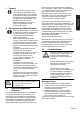
Vorwort Lesen Sie vor der Montage und der Inbetriebnahme diese Bedienungsanleitung aufmerksam und vollständig durch. Beachten Sie zu Ihrer eigenen Sicherheit und der Betriebssicherheit alle Warnungen und Hinweise. Wenn das Gerät nicht nach dieser Bedienungsanleitung benutzt wird, kann der vorgesehene Schutz beeinträchtigt werden.
2.3 Elektrische Installation Trennen Sie vor Installations- oder Wartungsarbeiten das Gerät von allen Spannungsquellen und stellen Sie GEFAHR sicher, dass keine BERÜHRGEFÄHRLICHEN Spannungen mehr vorhanden sind. AC-Versorgte Geräte dürfen nur über einen Schalter oder Leistungsschalter mit dem Niederspannungsnetz verbunden werden, welcher in der Nähe des Gerätes installiert und als dessen Trennvorrichtung gekennzeichnet ist.
3 Beschreibung • • • • • • • • • • • • • • • • 4 6-stellige 14-Segment-LED-Anzeige, 14 mm, zur Messwertanzeige und Dialogführung Zuschaltbare Laufschrift als Hilfetext Sprache für den Hilfetext in Deutsch oder Englisch wählbar Signaleingang für Dehnungsmessbrücken 3,3 mV/V, 3,0 mV/V, 2,0 mV/V, 1,5 mV/V und 1,0 mV/V Abtastrate 10 Messungen pro Sekunde Digitales Filter 1.
5 Blockschaltbild 6 Anschlussbelegung Seite 6
Bedienkonzept (Betriebsmode) deutsch 7 Seite 7
Programmierung Einstieg in das Programmiermenü + > 3 sec • Während der Programmierung sind die Relais inaktiv (nicht bestromt). • Beim Verlassen des Programmiermenü über SAVE werden Minimalwert, Maximalwert und Totalisatorwert gelöscht.
Funktion wählen / Parameter einstellen / Parameter übernehmen Funktion Parameter deutsch Funktionsgruppen Seite 9
9 Funktionsgruppen Werkseinstellungen sind grau hinterlegt. 9.1 Hilfetext (Laufschrift) Menü Hilfetext Wähle Hilfetext Ein - eine gestartete Laufschrift kann mit jeder Programmiertaste abgebrochen werden Aus Wähle Sprache für Hilfetext English Deutsch 9.2 Signaleingänge Menü Eingangssignal Wähle Messbereich Empfindlichkeit 3,3 mV/V Empfindlichkeit 3,0 mV/V Empfindlichkeit 2,0 mV/V Empfindlichkeit 1,5 mV/V Empfindlichkeit 1,0 mV/V Wähle Untere Messbereichsgrenze Wertebereich 0.00 … -105.
Anwender-Linearisierung Menü User-Linearisierung Wähle User-Linearisierung Linearisierung Aus Linearisierung Ein Wähle Anzahl der Linearisierungspunkte Wertebereich 3 … 12 Wähle Eingang-Anfangswert Wertebereich -105.00 … +105.00 [%] Wähle Anzeige-Anfangswert für INP.LO. Wertebereich -199999 … +999999 und DP Der Wertebereich für die Eingangswerte wird in % eingegeben. D.h. bei einer Sensorspannung von 10 V und einer Sensorempfindlichkeit von 3,3mV/V entsprechen 33mV einem Eingangswert von 100 %.
Beispiel für Lineare Skalierung Beispiel 1: -100 % … +100 % = -600 … 600 Beispiel 2: -60 % … +80 % = 300 … -400 Beispiel 3: 0 % … +100 % = 400 … 700 Beispiel für Nichtlineare Skalierung Seite 12
Funktion Multifunktionstaste (MP-Taste) und Multifunktionseingänge (MP-INP) Tarieren x x In Funktionsgruppe MP.KEY Funktion TARA auf ON programmieren. Im Betriebsmode den aktuellen Messwert (ACTUAL) wählen und MPTaste kurz betätigen. In Funktionsgruppe MP.INP Funktion MP.INP1 bzw. MP.INP2 auf TARA programmieren. Im Betriebsmode Multifunktions-Eingang 1 bzw. Multifunktionseingang 2 kurz aktivieren. Tarawert löschen x In Funktionsgruppe MP.KEY Funktion TARA auf ON programmieren.
9.4.1 Multifunktions-Taste 9.4.
Totalisatorfunktion Menü Totalisator Wähle Wert für Schleichmengenunterdrückung Wertebereich -199999 … +999999 und DP Wähle Wert für Multiplikationsfaktor Wertebereich 0.00001 … 9.99999 Wähle Skalierungsfaktor Skalierungsfaktor x 1 Skalierungsfaktor x 0,1 Skalierungsfaktor x 0,01 Skalierungsfaktor x 0,001 Skalierungsfaktor x 0,0001 Wähle Dezimalpunkt für Totalisator (anzeigend) 0 0.0 0.00 0.000 0.0000 0.00000 Mit einem ACK.
9.
deutsch Ansteuerung bei steigendem Messsignal Ansteuerung bei fallendem Messsignal Seite 17
Ansteuerung Bandbegrenzung 10 Messkreisüberwachung Messbereich 3,3 mV/V 3,0 mV/V 2,0 mV/V 1,5 mV/V 1,0 mV/V Signalisierung Untere Anzeigebereichsgrenze Obere Anzeigebereichsgrenze Untere Messbereichsgrenze Obere Messbereichsgrenze Ŷ Ŷ Ŷ Ŷ Ŷ Ŷ Ŷ Ŷ Ŷ Ŷ Ŷ Ŷ Ŷ Ŷ Ŷ Ŷ Ŷ Ŷ Ŷ Ŷ Fühler-/Leitungskurzschluss Fühler-/Leitungsbruch 1) 2) Ŷ Ŷ Ŷ Ŷ Ŷ blinkend blinkend blinkend blinkend blinkend (Ŷ = wird erkannt) 1) Leitungskurzschluss zwischen Signaleingang + und Signaleingang – wird nicht erkannt.
11 Technische Daten Allgemeine Daten Anzeige: Ziffernhöhe: Datensicherung: Bedienung: 11.2 6-stellige, 14-Segment-LED 14 mm > 10 Jahre, EEPROM 5 Tasten Messsignaleingänge Abtastrate: 10 Messungen/sec Eingangswiderstand: 1 M Max. Meßsignalbereich: ca. ± 35 mV Max. Spannung: ± 10V. Netzbrummunterdrückung: 11.6 Empfindlichkeit: Auflösung: Messgenauigkeit @ 23°C: Temperaturdrift: Empfindlichkeit: Auflösung: Messgenauigkeit @ 23°C: Temperaturdrift: 11.3 3,3 mV/V;3,0 mV/V;2,0 mV/V ± 15 Bit typ.
11.11 Anschlüsse Spannungsversorgung und Ausgänge: Schraubklemme, 8-polig, RM5,00 Aderquerschnitt, max. 2,5 mm² Signal- und Steuereingänge: Schraubklemme, 9-polig, RM 3,50 Aderquerschnitt, max.
13 Hilfstexte NO YES ON OFF DE EN 3.3MV/V 3.0MV/V 2.0MV/V 1.5MV/V 1.0MV/V 0 0.0 0.00 0.000 0.0000 0.00000 50HZ 60HZ NO YES OFF ON OFF ON OFF ON OFF ON OFF ON OFF ON KEINE PROGRAMMIERUNG PROGRAMMIERUNG STARTEN HAUPTMENUE HILFETEXT WAEHLEN HILFSTEXTE EIN HILFETEXT AUS SPRACHE DEUTSCH LANGUAGE ENGLISH HAUPTMENUE SIGNALEINGANG MESSBEREICH 3.3MV/V MESSBEREICH 3.0MV/V MESSBEREICH 2.0MV/V MESSBEREICH 1.5MV/V MESSBEREICH 1.
MP.INP. MP.INP.x MP.INP.x MP.INP.x MP.INP.x MP.INP.x MP.INP.x MP.INP.x MP.INP.x MP.INP.x MP.INP.x MP.INP.x MP.INP.x MP.INP.x TOTAL CUT.OFF FACTOR SCALE SCALE SCALE SCALE SCALE DP.TOT. DP.TOT. DP.TOT. DP.TOT. DP.TOT. DP.TOT ALARMx AL.OUTx AL.OUTx AL.OUTx ALLOC.x ALLOC.x MD.OUTx MD.OUTx MD.OUTx FM.OUTx FM.OUTx ON.HYS.x OF.HYS.x ON.DLY.x OF.DLY.x END.PRG. END.PRG. -1.9.9.9.9.9 9.9.9.9.9.9. OVERFL. UNDERF. SENSOR Seite 22 NO.FUNC. RES.MIN. RES.MAX. R.PEAKS RES.REL. DISP.HD. LOC.ALR. LOC.PRG. LOC.KEY TARA R.
CODIX 566 Process Controllers english for Strain Gauge inputs with Totaliser function Order code 6.56X.X1X.X0X Further outputs (optional) 0 = none 9 = analogue output (only for DC version) Supply voltage 0 = 100 … 240 V AC ± 10% 3 = 10 ...
Table of Contents (German is the original version.) 1 2 3 4 5 6 7 8 9 Preface Safety instructions and Warnings 3 3 2.1 2.2 2.3 2.4 3 3 4 4 Use according to the intended purpose Mounting in a control panel Electrical Installation Cleaning and maintenance Description Display/Operating elements Block diagram Connections Operating concept (Operating mode) Programming Function Groups 5 5 6 6 7 8 10 9.1 9.2 9.3 9.4 10 10 11 13 14 14 15 16 9.5 9.
Preface Please read this instruction manual entirely and carefully before installation and start-up. Please observe all warnings and advice, both for your own safety and for general plant safety. If the device is not used in accordance with this instruction manual, then the intended protection can be impaired. 2 Safety instructions and Warnings Please use the device only if its technical condition is perfect. It should be used only for its intended purpose.
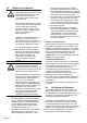
2.3 Electrical Installation The device must be disconnected from any power supply prior to any installation or maintenance work. DANGER Make sure that no more voltages x x LIABLE TO CAUSE AN ELECTROCUTION are present. AC-powered devices must only be connected to the low-voltage network via a switch or circuit breaker installed close to the device and marked as their disconnecting device.
3 Description Digital panel meter for displaying measured values, as well as monitoring limit values in industrial applications. • • • • • • • • • • • • • • • 4 6-digit 14-segment LED display, 14 mm, for displaying measured values and dialogs Running text can be switched on as Help Text Language for the Help Text selectable as English or German Signal input for strain gauges 3.3 mV/V, 3.0 mV/V, 2.0 mV/V, 1.5 mV/V and 1.
5 Block diagram 6 Connections Page 6
Operating concept (Operating mode) english 7 Page 7
8 Programming To enter the Programming menu + > 3 sec • During programming the relays are inactive (not energised). • When quitting the programming menu via SAVE, the minimum and maximum values and the totaliser value are all cleared.
Selecting Function / Setting Parameters / Accepting Parameters Function Parameter english Function Groups Page 9
9 Function Groups Factory settings are highlighted grey 9.1 Help Texts (running text) Input range -105.00 … +105.00 [%] Menu Input Signal Select display high value for INP.HI. Input range -199999 … +999999 and DP Select Input Filter The Filter function shows how many measurement cycles are used to determine the moving average.
9.3 User Linearisation Menu User Linearisation Linearisation ON Select number of linearisation (control) points Input range 3 … 12 Select input low value Input range -105.00 … +105.00 [%] Select display low value for INP.LO. Input range -199999 … +999999 and DP The input range for the input values is entered in %. This means that with a sensor voltage of 10 V and a sensor sensitivity of 3.3 mV / V then 33 mV equate to an input value of 100 %. The functions LO.LIM and HI.LIM limit the editable range.
Example for linear scaling Example 1: -100 % … +100 % = -600 … 600 Example 2: -60 % … +80 % = 300 … -400 Example 3: 0 % … +100 % = 400 … 700 Example for non-linear scaling Page 12
Function Multifunction Key (MP-Key) and Multifunction inputs (MP-INP) Tare x x In the function group MP.KEY, programme the function TARA to ON. In the operating mode select the current measured value (ACTUAL) and briefly press the MP Key. In the function group MP.INP, programme the function MP.INP1 or MP.INP2 to TARA. In the operating mode briefly activate the multifunction input 1 or multifunction input 2. Reset Tare Value x In the function group MP.KEY, programme the function TARA to ON.
9.4.
Totaliser function Menu Totaliser Select value for low threshold cut-off Input value range -199999 … +999999 and DP Select value for multiplication factor Input value range 0.00001 … 9.99999 Select scale factor Scale factor x 1 Scale factor x 0.1 Scale factor x 0.01 Scale factor x 0.001 Scale factor x 0.0001 Select decimal point for totaliser (optical function only) 0 0.0 0.00 0.000 0.0000 0.00000 Using ACK.
9.
english Control with incrementing measuring signal Control with decrementing measuring signal Page 17
Control with Band Limitation 10 Monitoring of Measuring Circuit Meas. range 3.3 mV/V 3.0 mV/V 2.0 mV/V 1.5 mV/V 1.0 mV/V Indication Lower Display Range limit Upper Display Range limit Lower Meas. Range limit Upper Meas. Range limit Ŷ Ŷ Ŷ Ŷ Ŷ Ŷ Ŷ Ŷ Ŷ Ŷ Ŷ Ŷ Ŷ Ŷ Ŷ Ŷ Ŷ Ŷ Ŷ Ŷ blinking blinking blinking blinking (Ŷ = is detected) 1) Wire short circuit between Signal input + and Signal input – is not detected. 2) Wire break with Sensor supply + or Sensor supply – is not detected.
11.1 General Data Display: Digit height: Data retention: Operation: 11.2 DC supply: 6-digit, 14 segment LED 14 mm > 10 years, EEPROM 5 keys Measuring signal inputs Sampling rate: Input resistance: Max. measuring signal range: Max. voltage 11.6 10 readings/sec 1 M for DC-supply: approx. ± 35 mV ±10 V. 11.7 3.3 mV/V; 3.0 mV/V; 2.0 mV/V Resolution: ± 15 Bit Measuring accuracy typ. 0.05 % of range @ 23°C: max. 0.1 % of range Temperature drift: < 100 ppm/K Noise emission: 11.
11.11 Connections Supply voltage and outputs: Plug-in screw terminal, 8-pin, RM5.00 Core cross-section, max. 2.5 mm Signal and control inputs: Plug-in screw terminal, 9-pin, RM 3.50 Core cross section, max. 1.
PROG. NO NO PROGRAMMING PROG. HLP.TXT. HLP.TXT. HLP.TXT SL.LANG. SL.LANG. INPUT. RANGE RANGE RANGE RANGE RANGE LO.LIM. HI.LIM. DP. DP. DP. DP. DP. DP. INP.LO. DISP.LO. INP.HI. DISP.HI. FILTER PW.DELY. PW.FREQ. PW.FREQ. LINEAR. LINEAR. LINEAR. NUM.PNT. INP.01 DISP.01 to INP.10 DISP.10 MP.KEY TARA TARA RES.MIN. RES.MIN. RES.MAX. RES.MAX. RES.REL. RES.REL. RES.TOT. RES.TOT. ACK.TOT.
ACK.TOT. MP.INP. MP.INP.x MP.INP.x MP.INP.x MP.INP.x MP.INP.x MP.INP.x MP.INP.x MP.INP.x MP.INP.x MP.INP.x MP.INP.x MP.INP.x MP.INP.x TOTAL CUT.OFF FACTOR SCALE SCALE SCALE SCALE SCALE DP.TOT. DP.TOT. DP.TOT. DP.TOT. DP.TOT. DP.TOT ALARMx AL.OUTx AL.OUTx AL.OUTx ALLOC.x ALLOC.x MD.OUTx MD.OUTx MD.OUTx FM.OUTx FM.OUTx ON.HYS.x OF.HYS.x ON.DLY.x OF.DLY.x END.PRG. END.PRG. -1.9.9.9.9.9 9.9.9.9.9.9. OVERFL. UNDERF. SENSOR Page 22 ON NO.FUNC. RES.MIN. RES.MAX. R.PEAKS RES.REL. DISP.HD. LOC.ALR. LOC.PRG. LOC.
CODIX 566 Contrôleurs de process français pour jauges de contrainte avec fonction totalisateur Référence de commande 6.56X.X1X.
Sommaire (La version allemande constitue la version originale.) 1 2 3 4 5 6 7 8 9 Introduction Instructions de sécurité et avertissements 3 3 2.1 2.2 2.3 2.4 3 3 4 4 Utilisation conforme Montage encastré Installation électrique Nettoyage et entretien Description Organes de visualisation/de commande Synoptique Raccordement Concept d’utilisation (mode marche) Programmation Groupes de fonctions 5 5 6 6 7 8 10 9.1 9.2 9.3 9.
Introduction Lisez entièrement et attentivement ces instructions d’utilisation avant le montage et la mise en service. Pour votre propre sécurité, ainsi que pour la sécurité de fonctionnement, respectez tous les avertissements et indications. Une utilisation de l’appareil non conforme à ces instructions peut affecter la protection prévue.
2.3 Installation électrique Avant tout travail d’installation ou de maintenance, déconnecter l’appareil de toutes les sources d’alimentation DANGER et s’assurer de l’absence de toute x TENSION POUVANT OCCASIONNER UNE ELECTROCUTION. Les appareils alimentés en courant alternatif ne peuvent être reliés au réseau basse tension que par l’intermédiaire d’un interrupteur ou d’un sectionneur de puissance installé à proximité de l’appareil et repéré comme le dispositif de coupure de cet appareil.
3 Description Afficheur digital pour l’affichage de valeurs mesurées et pour la surveillance de valeurs limite dans le domaine industriel.
5 Synoptique 6 Raccordement Page 6
Concept d’utilisation (mode marche) ou ou ou MODE MARCHE Val. mesurée courante Valeur min. Valeur max. Version de l’appareil pdt 2s Version de logiciel pdt 2s ou Total TOUCHE MP FONCTION DE LA TOUCHE, voir 9.
8 Programmation Appel du menu de programmation + > 3 sec • Les relais sont inactifs (non alimentés) pendant la programmation). • Les valeurs minimale, maximale et le totalisateur sont effacés lorsque le menu de programmation est refermé avec SAVE.
Sélection de la fonction / Réglage des paramètres / Prise en compte des paramètres Fonction Paramètres Sélection du paramètre Réglage de la valeur Réduction de la valeur Augmentation de la valeur Sélection du digit Sélection du paramètre Page 9 français Groupes de fonctions
9 Groupes de fonctions Les réglages d’usine sont indiqués sur fond gris. 9.1 Menu Signal d’entrée Plage de valeurs -105.00 … +105.00 [%] Valeur à afficher finale pour INP.HI. Plage de valeurs -199999 … +999999 et DP Filtre d’entrée La fonction Filtre permet de déterminer le nombre de cycles de mesure à utiliser pour la formation de la moyenne flottante.
9.3 Linéarisation utilisateur Menu Linéarisation utilisateur Linéarisation utilisateur Linéarisation désactivée Linéarisation activée Nombre de points de linéarisation Plage de valeurs 3 … 12 Valeur d’entrée initiale Plage de valeurs -105.00 … +105.00 [%] Valeur à afficher initiale pour INP.LO. Plage de valeurs -199999 … +999999 et DP La plage de valeurs des valeurs d’entrée est saisie en % : p. ex.
Exemple d’une échelle linéaire Exemple 1 : -100 % … +100 % = -600 … 600 Exemple 2 : -60 % … +80 % = 300 … -400 Exemple 3 : 0 % … +100 % = 400 … 700 Affichage Exemple 3 Exemple 2 Exemple 1 Valeur d’entrée Exemple d’une échelle non linéaire Affichage Exemple 2 Exemple 1 Valeur d’entrée Page 12
Fonction Touche multifonctions (touche MP) et Entrées multifonctions (MP-INP) Tare x x Dans le groupe de fonctions MP.KEY, programmer la fonction TARA à ON. En mode marche, sélectionner la valeur mesurée courante (ACTUAL) et presser brièvement la touche MP. Dans le groupe de fonctions MP.INP, programmer la fonction MP.INP1 ou MP.INP2 à TARA. En mode marche, activer brièvement l’entrée multifonctions programmée, 1 ou 2. RES.REL.
9.4.
Fonction totalisateur Point décimal pour le totalisateur (pour l’affichage) 0 0.0 0.00 0.000 0.0000 0.00000 Menu Totalisateur Valeur de coupure en cas de valeurs mesurées trop faibles Plage de valeurs -199999 … +999999 et DP Valeur du facteur de multiplication Plage de valeurs 0.00001 … 9.99999 Valeur du facteur d’échelle Facteur d’échelle x 1 Facteur d’échelle x 0,1 Facteur d’échelle x 0,01 Facteur d’échelle x 0,001 Facteur d’échelle x 0,0001 ACK.
Surveillance des valeurs limite Menu Sortie d’alarme 1 Sélection du mode opératoire Désactivée Réinitialisation automatique du relais à la fin de l’alarme Pas de réinitialisation auto.
Commande par signal de mesure croissant Tempo Temps ON Tempo OFF Point de commutation ON Valeur hystérèse ON Valeur limite Valeur hystérèse OFF Point de commutation OFF Valeur du process Avec hystérèse / avec tempo. Sans hystérèse / sans tempo. Avec hystérèse / avec tempo. Sans hystérèse / sans tempo.
Commande par limitation de bande passante Tempo ON Tempo OFF Tempo ON Tempo OFF Tempo OFF BANDE PASSANTE Point de commutation HAUT Valeur hystérèse ON Valeur limite Valeur hystérèse OFF Point de commutation BAS Valeur du process Avec tempo. Sans tempo. Avec tempo. Sans tempo.
11 Caractéristiques techniques 11.5 11.1 Alimentation AC : Affichage : Hauteur des chiffres : Sauvegarde des données : Commande : 11.2 LED, 6 digits de 14 segments 14 mm > 10 ans, EEPROM par 5 touches Entrées de signal de mesure Vitesse d’échantillonnage : 10 mesures/sec. Résistance d’entrée : 1 M Plage max. du signal de mesure : env. ± 35 mV Tension max. : ± 10V.
EN60068-2-6 Résist. aux chocs : EN60068-2-27 EN60068-2-29 30 min dans chaque direction 100G / XYZ 3 fois dans chaque direction 10G / 6 ms / XYZ 2000 fois dans chaque direction 11.11 Raccordements Tension d’alimentation et sorties : Bornes à visser, 8 bornes, pas 5,00 Section des conducteurs : max. 2,5 mm² Entrées de signal et de commande : Bornes à visser, 9 bornes, pas 3,50 Section des conducteurs : max.
13 Textes d’aide NO YES ON OFF DE EN 3.3MV/V 3.0MV/V 2.0MV/V 1.5MV/V 1.0MV/V 0 0.0 0.00 0.000 0.0000 0.00000 50HZ 60HZ NO YES OFF ON OFF ON OFF ON OFF ON OFF ON OFF NO PROGRAMMING START PROGRAMMING MAIN MENU SELECT HELPTEXT HELPTEXTS ON HELPTEXTS OFF SPRACHE DEUTSCH LANGUAGE ENGLISH MAIN MENU SIGNAL INPUT INPUT RANGE 3.3MV/V INPUT RANGE 3.0MV/V INPUT RANGE 2.0MV/V INPUT RANGE 1.5MV/V INPUT RANGE 1.0MV/V LOWER INPUT RANGE LIMIT UPPER INPUT RANGE LIMIT NO DECIMAL POINT DECIMAL POINT 0.0 DECIMAL POINT 0.
ACK.TOT. MP.INP. MP.INP.x MP.INP.x MP.INP.x MP.INP.x MP.INP.x MP.INP.x MP.INP.x MP.INP.x MP.INP.x MP.INP.x MP.INP.x MP.INP.x MP.INP.x TOTAL CUT.OFF FACTOR SCALE SCALE SCALE SCALE SCALE DP.TOT. DP.TOT. DP.TOT. DP.TOT. DP.TOT. DP.TOT ALARMx AL.OUTx AL.OUTx AL.OUTx ALLOC.x ALLOC.x MD.OUTx MD.OUTx MD.OUTx FM.OUTx FM.OUTx ON.HYS.x OF.HYS.x ON.DLY.x OF.DLY.x END.PRG. END.PRG. -1.9.9.9.9.9 9.9.9.9.9.9. OVERFL. UNDERF. SENSOR Page 22 ON NO.FUNC. RES.MIN. RES.MAX. R.PEAKS RES.REL. DISP.HD. LOC.ALR. LOC.PRG. LOC.
CODIX 566 Controllore di processo Codice di ordinazione 6.56X.X1X.X0X Altre uscite (opzionali) 0 = nessuna 9 = uscita analogica (unicamente versione DC) Tensione di alimentazione 0 = 100 … 240 V AC ± 10% 3 = 10 ...
Indice 1 2 3 4 5 6 7 8 9 Introduzione Istruzioni di sicurezza e avvertenze 3 3 2.1 2.2 2.3 2.4 3 3 4 4 Utilizzo conforme Montaggio incassato Installazione elettrica Pulizia e manutenzione Descrizione Display/Elementi di controllo Schema a blocchi Collegamento Concetto di utilizzo (modalità di funzionamento) Programmazione Gruppi funzioni 5 5 6 6 7 8 10 9.1 9.2 9.3 9.4 10 10 11 13 14 14 15 16 9.5 9.
Introduzione Prima di procedere al montaggio ed alla messa in funzione, leggere attentamente e completamente le presenti istruzioni d’uso. Per salvaguardare la vostra sicurezza e la sicurezza di funzionamento, rispettare tutte le avvertenze ed indicazioni. Un uso improprio dell’apparecchio può pregiudicare la protezione prevista.
2.3 Installazione elettrica Prima di qualsiasi intervento di installazione o di manutenzione, interrompere la tensione di PERICOLO alimentazione dell’apparecchio e assicurarsi che non siano presenti TENSIONI CON PERICOLO DI ELETTROCUZIONE.
3 Descrizione Display digitale per la visualizzazione di valori di misurazione e per la sorveglianza di valori limite nell'area di utilizzo industriale.
5 Schema a blocchi Versione DC: Versione AC: 6 Collegamento Pagina 6
Concetto di utilizzo (modalità di funzionamento) o o o MODALITA' DI FUNZIONAMENTO Val. di misura attuale Valore min. Valore max. Versione apparecchio per 2s Versione software per 2s o Totale TASTO MP FUNZIONE DEL TASTO, vedi 9.4 o Valore limite 1 Regolazione val. limite 1 Valore limite 2 Regolazione val.
8 Programmazione Entrata nel menu di programmazione + > 3 sec • Durante la programmazione i relè non sono attivi (non alimentati). • Quando si lascia il menu di programmazione attraverso SAVE, il valore minimo, quello massimo e il valore del totalizzatore vengono cancellati.
Scelta della funzione / Impostazione dei parametri / Acquisizione dei parametri Funzione Parametro Selezione del parametro Regolazione del valore Riduzione del valore Aumento del valore Selezione del digit Selezione del parametro español italiano Gruppo funzioni Pagina 9
9 Gruppi funzioni Le impostazioni di fabbrica presentano uno sfondo grigio. 9.
9.3 Linearizzazione utente Menu Linearizzazione utente Linearizzazione attivata Il campo dei valori d’entrata viene indicato in %. Significa che per una tensione dei sensori di 10V e una sensibilità dei sensori di 3,3mV/V, 33mV corrispondono ad un valore in ingresso pari al 100% Numero dei punti di linearizzazione Le funzioni LO.LIM e HI.LIM delimitano l'area editabile. Linearizzazione utente Linearizzazione disattivata Campo di valori 3 … 12 Valore di entrata iniziale Campo di valori -105.00 … +105.
Esempio di scala lineare Esempio1: -100% … +100% = -600 … 600 Esempio 2: -60% … +80% = 300 … -400 Esempio 3: 0% … +100% = 400 … 700 Display Esempio 3 Esempio 2 Esempio 1 Valore d’entrata Esempio di scala non lineare Display Esempio 2 Esempio 1 Valore d’entrata Pagina 12
9.4 Funzione tasto multifunzione (tasto MP) e entrate multifunzione (MP-INP) x Nel gruppo funzioni MP.INP, programmare la funzione MP.INP1 oppure MP.INP2 su RES.REL. In modalità funzionamento, attivare brevemente l'entrata multifunzione programmata, 1 o 2. Taratura x Nel gruppo funzioni MP.KEY, programmare la funzione TARA su ON. In modalità funzionamento, scegliere il valore di misurazione attuale (ACTUAL) e premere brevemente il tasto MP. Nel gruppo funzioni MP.INP, programmare la funzione MP.
9.4.1 Tasto multifunzione 9.4.
Funzione totalizzatore Punto decimale per il totalizzatore (indicativo) 0 0.0 0.00 0.000 0.0000 0.00000 Menu totalizzatore Valore per l’interruzione in caso di portata troppo bassa Campo di valori -199999 … + 999999 e DP Valore per il fattore di moltiplicazione Campo di valori 0.00001 … 9.99999 Fattore di scala Fattore di scala x 1 Fattore di scala x 0,1 Fattore di scala x 0,01 Fattore di scala x 0,001 Fattore di scala x 0,0001 Con un ACK.
9.6 Sorveglianza dei valori limite Menu uscita d’allarme 1 Tipo di esercizio Disattivato Ripristino automatico del relè alla fine dell’alarme Senza ripristino automatico del relè alla fine dell’alarme - non in caso di limitazione della banda passante Attivazione dell'uscita allarme 1 Comando dell’uscita Segnale di misurazione crescente Segnale di misurazione decrescente Limitazione di banda passante.
Comando con segnale di misurazione crescente Ritardo Temps ON Ritardo OFF Punto di commutazione ON Valeur hystérèse ON Valore isteresi OFF Punto di commutazione OFF Valore del processo Con isteresi / con ritardo Senza isteresi / senza ritardo Con isteresi / con ritardo Senza isteresi / senza ritardo Tasto multifunzione o entrata multifunzione Tempo español italiano Comando con segnale di misurazione decrescente Pagina 17
Comando con limitazione di banda passante Ritardo ON Ritardo OFF Ritardo ON Ritardo OFF Ritardo OFF BANDA PASSANTE Punto di commutazione ALTO Valore isteresi ON Valore limite Valore isteresi OFF Punto di commutazione BASSO Valore del processo Con ritardo Senza ritardo Con ritardo Senza ritardo Tempo 10 Sorveglianza del circuito di misurazione Campo di misurazione 3,3 mV/V 3,0 mV/V 2,0 mV/V 1,5 mV/V 1,0 mV/V Limite inferiore del campo di visualizzazione Limite superiore del campo di visualizza
11.5 11 Dati tecnici Dati generali Display Altezza delle cifre Sicurezza dati Utilizzo 11.2 LED a 6 cifre e 14 segmenti 14 mm > 10 anni, EEPROM 5 Tasti Entrate dei segnali di misurazione Frequenza di campionamento Resistenza d'entrata Campo max. di segnale di misura Tensione max. 10 misurazioni/sec 1 M ca. ± 35mV ± 10V. Ingresso del segnale dell’estensimetro Sensibilità 3,3mV/V;3,0 mV/V;2,0 mV/V Risoluzione ± 15 bit Precisione di misurazione @ 23°C tip. 0,05% (su tutto il campo di misurazione) max.
Indice di protezione: IP 65 (frontale, solo l’apparecchio) Materiale della scatola: Policarbonato UL94 V-2 Resistenza alle vibrazioni EN60068-2-6: 10 - 55 Hz / 1 mm / XYZ 30 min in ogni direzione Resistenza agli urti: EN60068-2-27 100G / XYZ 3 volte in ogni direzione EN60068-2-29 10G / 6 ms/ XYZ 2000 volte in ogni direzione 12 Dimensioni Dimensioni in mm [inch] Apertura d’incastro: 92+0,8 x 45+0,6 Pagina 20 11.
13 Testi di aiuto MP.INP. MP.INP.x MP.INP.x NO YES ON OFF DE EN 3.3MV/V 3.0MV/V 2.0MV/V 1.5MV/V 1.0MV/V 0 0.0 0.00 0.000 0.0000 0.00000 50HZ 60HZ NO YES OFF ON OFF ON OFF ON OFF ON OFF ON OFF ON NO.FUNC. RES.MIN. NO PROGRAMMING START PROGRAMMING MAIN MENU SELECT HELPTEXT HELPTEXTS ON HELPTEXTS OFF SPRACHE DEUTSCH LANGUAGE ENGLISH MAIN MENU SIGNAL INPUT INPUT RANGE 3.3MV/V INPUT RANGE 3.0MV/V INPUT RANGE 2.0MV/V INPUT RANGE 1.5MV/V INPUT RANGE 1.
MP.INP.x MP.INP.x MP.INP.x MP.INP.x MP.INP.x MP.INP.x MP.INP.x MP.INP.x MP.INP.x MP.INP.x MP.INP.x TOTAL CUT.OFF FACTOR SCALE SCALE SCALE SCALE SCALE DP.TOT. DP.TOT. DP.TOT. DP.TOT. DP.TOT. DP.TOT ALARMx AL.OUTx AL.OUTx AL.OUTx ALLOC.x ALLOC.x MD.OUTx MD.OUTx MD.OUTx FM.OUTx FM.OUTx ON.HYS.x OF.HYS.x ON.DLY.x OF.DLY.x END.PRG. END.PRG. -1.9.9.9.9.9 9.9.9.9.9.9. OVERFL. UNDERF. SENSOR Pagina 22 RES.MAX. R.PEAKS RES.REL. DISP.HD. LOC.ALR. LOC.PRG. LOC.KEY TARA R.TARA RES.TOT ACK.TOT x1 x0.1 x0.01 x0.
CODIX 566 Controlador de proceso para puentes extensométricos con función de totalizador Clave de pedido 6.56X.X1X.X0X Tensión de alimentación 0 = 100 … 240 V AC ± 10% 3 = 10 ...
Índice 1 2 3 4 5 6 7 8 9 Introducción Observaciones de seguridad y advertencia 3 3 2.1 2.2 2.3 2.4 3 3 4 4 Uso conforme a su finalidad Montaje en el cuadro de mando Instalación eléctrica Limpieza y Mantenimiento Descripción Órganos de visualización/de mando Diagrama funcional Conexiones Concepto de manejo (modo de servicio) Programación Grupos de funciones 5 5 6 6 7 8 10 9.1 9.2 9.3 9.4 10 10 11 13 14 14 15 16 9.5 9.
Antes del montaje y de la puesta en servicio, lea completa y detenidamente estas instrucciones de manejo. Por su propia seguridad y la del servicio, respete todas las advertencias y observaciones. Si no se emplea el aparato según se indica en estas instrucciones, se puede poner en peligro la protección prevista.
2.3 Instalación eléctrica Antes de realizar trabajos de instalación o mantenimiento, separe el aparato de todas las fuentes de PELIGRO tensión y asegúrese de que no haya ninguna TENSIÓN QUE PODRÍA PROVOCAR UNA ELECTROCUCIÓN. Los aparatos alimentados por CA sólo se pueden unir con la red de baja tensión a través de un interruptor o seccionador de potencia que está instalado cerca del aparato y que viene marcado como su dispositivo de desconexión.
3 Descripción Visualizador digital para la representación de valores de medición así como la supervisión de valores límite en el ámbito de empleo industrial. • • • • • • • • • • • • • • • • 4 Visualizador LED de 6 dígitos, 14 segmentos, 14 mm, para la visualización de valores de medición y el guiado interactivo. Texto de ayuda móvil conmutable. Lengua para el texto de ayuda seleccionable en alemán o inglés.
5 Diagrama funcional 6 Conexiones Página 6
Concepto de manejo (modo de servicio) o o o MODO DE SERVICIO Val. medido corriente Valor mín. Valor máx. Versión apataro durante 2s Versión software durante 2s o Total TECLA MP FUNCIÓN DE LA TECLA, ver 9.
8 Programación Acceso al menú de programación + >3 seg • Durante la programación están inactivos los relés (no energizados). • Al salir del menú de programación con SAVE se borra el valor mínimo, el valor máximo y el valor del totalizador.
Elección de la función / Ajuste de los parámetros/ Confirmación de los parámetros Función Parámetro Selección del parámetro Ajuste del valor Reducción del valor Aumento del valor Selección del dígito Selección del parámetro español Grupo de funciones Página 9
9 Grupos de funciones Los valores de fábrica se indican en gris. 9.1 Texto de ayuda (texto móvil) Menú del texto de ayuda Texto de ayuda Activado - un texto móvil puede terminarse con cualquiera tecla de programación Desactivado Lengua del texto de ayuda Inglés Alemán 9.
9.3 Linealización usuario Menú Linealización usuario Linealización usuario Linealización desactivada Linealización activada Número de puntos de linealización Intervalo de valores 3 … 12 Valor de entrada inicial Intervalo de valores -105.00 … +105.00 [%] Valor de visualización inicial para INP.LO. Intervalo de valores -199999 … +999999 y DP El intervalo de valores para el valor de entrada se introducirá en %.
Ejemplo para una escala lineal Ejemplo 1: -100% … +100% = -600 … 600 Ejemplo 2: -60% … +80% = 300 … -400 Ejemplo 3: 0% … +100% = 400 … 700 Pantalla Ejemplo 3 Ejemplo 2 Ejemplo 1 Valor de entrada Ejemplo para una escala no lineal Pantalla Ejemplo 2 Ejemplo 1 Valor de entrada Página 12
Función Tecla multifunción (Tecla MP) y Entradas multifunción (MP-INP) Taraje x x Programe en el grupo de funciones MP KEY la función TARA en ON. En el modo de servicio seleccione el valor de medición corriente (ACTUAL) y accione brevemente la tecla MP. Programe en el grupo de funciones MP INP la función MP INP1 o MP INP2 en TARA. En el modo de servicio, active brevemente la entrada multifunción programada, 1 o 2. Borrar el valor de tara x Programe en el grupo de funciones MP KEY la función TARA en ON.
9.4.1 Tecla Multifunción 9.4.
Función totalizador Menú totalizador Valor para la interrupción por bajo caudal Intervalo de valores -199999 … +999999 y DP Valor para el factor de multiplicación. Intervalo de valores 0.00001 … 9.99999 Factor de escala Factor de escala x 1 Factor de escala x 0,1 Factor de escala x 0,01 Factor de escala x 0,001 Factor de escala x 0,0001 Punto decimal para el totalizador(indicativo) 0 0.0 0.00 0.000 0.0000 0.00000 Con un ACK.TOT se añadirá el valor de medición actual (caudal) a la memoria total general.
9.6 Supervisión de los valores limite Estado de la alarma Menú salida de alarma 1 Salida activa en caso de alarma Modo de funcionamiento Salida inactiva en caso de alarma Desactivado Histéresis de activación Modo reinicialización automática Intervalo de valores 0 … +9999 y DP Histéresis de desactivación -sólo en modo reinicialización auto. Intervalo de valores 0 … +9999 y DP Modo sin reinicialización auto.
Mando con señal de medición creciente Retardo Temps ON Retardo OFF Punto de conmutación ON Valor histéresis Valeur hystérèseON ON Valor límite Valor histéresis OFF Punto de conmutación OFF Valor del proceso Con histéresis / con retardo Sin histéresis / sin retardo Con histéresis / con retardo Sin histéresis / sin retardo Tecla multifonción o entrada multifonción Tiempo español Mando con señal de medición decreciente Página 17
Mando con limitación de banda Retardo ON Retardo OFF Retardo ON Retardo OFF Retardo OFF BANDA Punto de comutación ALTO Valor histéresis ON Valor límite Valor histéresis OFF Punto de comutación BAJO Valor del proceso Con retardo Sin retardo Con retardo Sin retardo Tiempo 10 Supervisión en el circuito de medición Intervalo de medición 3,3 mV/V 3,0 mV/V 2,0 mV/V 1,5 mV/V 1,0 mV/V Señalización Límite inferior del intervalo de visualización Límite superior del intervalo de visualización Límite in
11 Datos técnicos 11.5 11.1 Alimentación AC: Visualización: Tamaño de los dígitos: Salvaguarda de datos: Manejo: 11.2 LED, 6 dígitos, 14 segmentos 14 mm > 10 Años, EEPROM 5 teclas Entrada de señal de puente extensométrico Sensibilidad 3,3 mV/V; 3,0 mV/V; 2,0 mV/V Resolución: ± 15 bits Precisión de medición @ 23°C: tip. 0,05 % (intervalo de medición completo) máx. 0,1 % Deriva de temperatura: < 100 ppm/K Sensibilidad: 1,5 mV/V; 1,0 mV/V Resolución: ± 14 bits Precisión de medición @ 23°C: tip.
cuadro de mando: 92+0,8 x 45+0,6 mm Prof. de montaje: aprox. 92 mm inc. bornes Peso: aprox.
13 Textos de ayuda NO YES ON OFF DE EN 3.3MV/V 3.0MV/V 2.0MV/V 1.5MV/V 1.0MV/V 0 0.0 0.00 0.000 0.0000 0.00000 50HZ 60HZ NO YES OFF ON OFF ON OFF ON OFF ON OFF ON OFF ON NO PROGRAMMING START PROGRAMMING MAIN MENU SELECT HELPTEXT HELPTEXTS ON HELPTEXTS OFF SPRACHE DEUTSCH LANGUAGE ENGLISH MAIN MENU SIGNAL INPUT INPUT RANGE 3.3MV/V INPUT RANGE 3.0MV/V INPUT RANGE 2.0MV/V INPUT RANGE 1.5MV/V INPUT RANGE 1.0MV/V LOWER INPUT RANGE LIMIT UPPER INPUT RANGE LIMIT NO DECIMAL POINT DECIMAL POINT 0.
MP.INP. MP.INP.x MP.INP.x MP.INP.x MP.INP.x MP.INP.x MP.INP.x MP.INP.x MP.INP.x MP.INP.x MP.INP.x MP.INP.x MP.INP.x MP.INP.x TOTAL CUT.OFF FACTOR SCALE SCALE SCALE SCALE SCALE DP.TOT. DP.TOT. DP.TOT. DP.TOT. DP.TOT. DP.TOT ALARMx AL.OUTx AL.OUTx AL.OUTx ALLOC.x ALLOC.x MD.OUTx MD.OUTx MD.OUTx FM.OUTx FM.OUTx ON.HYS.x OF.HYS.x ON.DLY.x OF.DLY.x END.PRG. END.PRG. -1.9.9.9.9.9 9.9.9.9.9.9. OVERFL. UNDERF. SENSOR Página 22 NO.FUNC. RES.MIN. RES.MAX. R.PEAKS RES.REL. DISP.HD. LOC.ALR. LOC.PRG. LOC.KEY TARA R.
R60362.0009-Index C Kübler Group Fritz Kübler GmbH Schubertstrasse 47 D-78054 Villingen-Schwenningen Germany Tel: +49 7720 3903 - 0 Fax +49 7720 21564 info@kuebler.com www.kuebler.