
User manual

english
Page 5 | ENG
english
Screw terminal
6:
Common GND connection
for all inputs
Screw terminal
7:
(–) external power supply for the backlight option
Screw terminal
8:
(+) external power supply for the backlight option
(24 V DC ±20 %, 50 mA), Fuse T0.08 A, delayed action
All low voltages, SELV, reinforced/double
insulation.
Signal inputs must be protected with an exter-
nal delayed T0.01 A fuse when the source
does not provide protective impedance (fuse/
current limitation).
Screw terminal 1:
Timer Enable Input: time measurement as long as
the level at this input is high.
Optocoupler input 10…260 V AC/DC
galvanic isolation, active for
High signal
Low level: 0…2 V AC/V DC
High level: 10…260 V AC/DC
Input resistance: approximately 160 kOhm
AC mains frequency: 50/60Hz
Screw terminal 2:
Common AC/DC, common connection for the optocoup-
ler inputs (screw terminals 1 and 3)
Screw terminal 3:
Reset input: active for high level.
Optocoupler input: 10…260 V AC/DC galvanic
isolation, active for high signal
Min. pulse duration: 16 ms
Max. frequency: approximately 30 Hz
Low level: 0…2 V AC/V DC
High level: 10…260 V AC/DC
Input resistance: approximately 160 kOhm
AC mains frequency: 50/60Hz
Screw terminal
4:
Electrical locking of the reset key
Contact input / Open Collector NPN
(switching at 0 V DC)
Low level: 0…0.7 V DC
High level: 3…5 V DC
Input resistance:
approximately
2.2 MOhm
Input not active: Reset key locked
Input in contact with GND:
Reset key unlocked
Screw terminal 5:
Time range switching (Mode)
Contact input / Open Collector NPN
(switching at 0 V DC)
Low level: 0…0.7 V DC
High level: 3…5 V DC
Input resistance: approximately 2.2 MOhm
Function: see table 3
Note:
If the time range is changed during operati-
on,
the device must be reset, otherwise the
counting value will not be reproducible.
!
DANGER
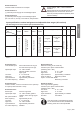
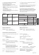
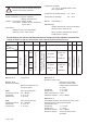
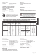
Input specification, terminal assignment and adjustable time ranges (AC versions)
The time range is set via a control input (screw terminal 5).
Screw terminal No. 1 No. 2 No. 3 No. 4 No. 5 No. 6 No. 7 No. 8
Designation
Model
INP A
AC/DC
Common
AD/DC
INP B
AC/DC
Reset
Enable
Time range (Mode) GND BL
–
BL
+
6.134.012.8x3
Timer Enable Input AC/DC
Common connection for
INP A and INP B
Reset input AC/DC
NPN reset key locking input,
Contact with GND. Key free.
not active
=
99999 h 59 m
contact with
GND
=
99999,99 h
GND = 0 V DC
Backlighting (–)
Backlighting (+)
6.135.012.8x3
not active
=
9999 h 59 m
59 s
contact with
GND
=
9999999,9 s
Table 3
t