User's Manual

Management Application Structure
E1 Spread Spectrum Radios
9-3
Figure 9-2 Managment via Local Equipment(Cascading)
Please refer to example 1 for configuration of Point-to-Point. This example focuses on configuration of
cascading.
Table 9-2 Example for managerial application(2)
Item Modem 1 Modem 2 Note
ETH(10BaseT) IP
192.168.168.1 192.168.100.1 Refer to section 8.1.5
ETH(10BaseT) Mask
255.255.255.0 255.255.255.0 Refer to section 8.1.5
NMS2 Data Rate
115200 N/A Refer to section 8.1.2
NMS2 Usage
Master Modem N/A Refer to section 8.1.2
NMS2 Local IP
10.0.0.1 N/A Refer to section 8.1.2
NMS2 Peer IP
10.0.0.2 N/A Refer to section 8.1.2
NMS2 Interface
Activation
Enable N/A Refer to section 8.1.2
NMS1 Data Rate
N/A 19200 Refer to section 8.1.1
NMS1 Usage
N/A Slave Modem Refer to section 8.1.1
NMS1 Local IP
N/A 10.0.0.2 Refer to section 8.1.1
NMS1 Peer IP
N/A 10.0.0.1 Refer to section 8.1.1
NMS1 Interface
Activation
N/A Enable Refer to section 8.1.1
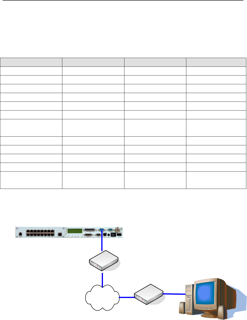
9.3 Remote Management via External Modem
The following shows how to remote manage via external modem.
NMS2
Computer for monitor
Dialup Modem
PSTN
Dialup Modem
Modem 1


