User's Manual

Management Application Structure
E1 Spread Spectrum Radios
9-2
IP Forwarding
Forwarding Forwarding Refer to section 8.1.7
IP Route Destination
192.168.100.0 Refer to section 8.1.8
IP Route Subnet Mask
255.255.255.0 Refer to section 8.1.8
IP Route Interface
Link Refer to section 8.1.8
IP Route Gateway
10.0.0.2 Refer to section 8.1.8
Default Gateway
Interface
Ethernet Link Refer to section 8.1.8
Default Gateway
192.168.168.100 10.0.0.1 Refer to section 8.1.8
Trap/Trap Alarm Setting
All All Refer to section 8.1.9
Trap/Destination
192.168.168.100 192.168.168.100 Refer to section 8.1.9
Trap/Community
Private private Refer to section 8.1.9
Item Computer Note
IP
192.168.168.100 The same subnet with
modem 1
Subnet Mask
255.255.255.0
Default Gateway
192.168.168.1
Route add 192.168.100.0 mask 255.255.255.0 192.168.168.1
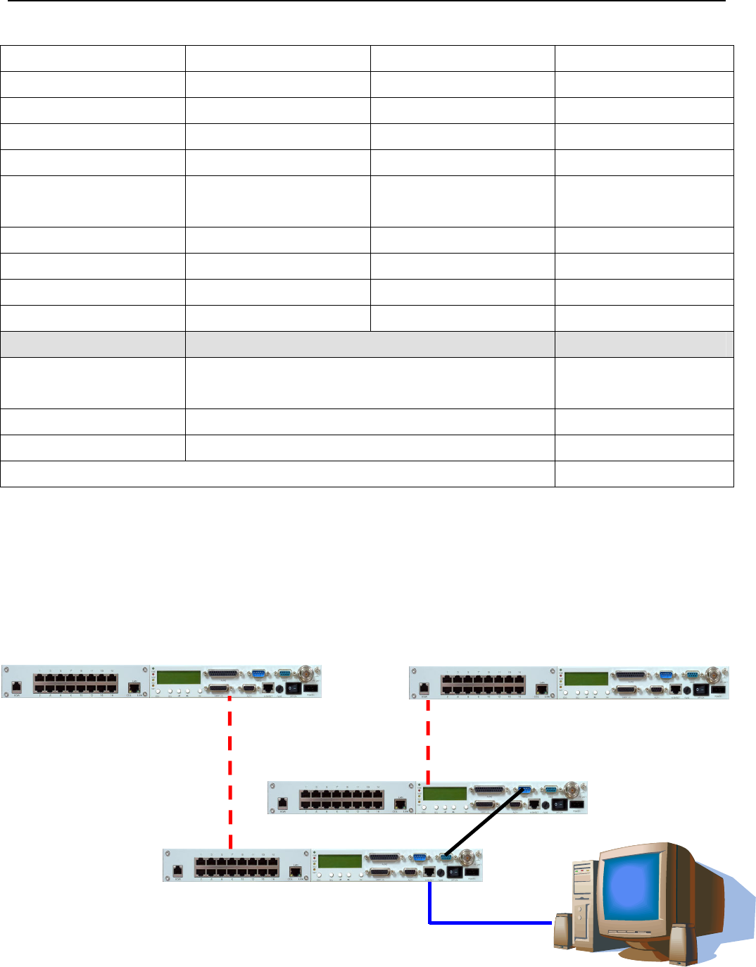
9.2 Managment via Local Equipment(Cascading)
The following diagram is cascading mode. Multiple systems should interconnect NMS2-NMS1 with RS-232
cable to communicate all the monitor signals.
NMS2
NMS1
ETH
RF Link Connection
Computer for monitor
Modem 1
Modem 2


