
User guide


KT2 - KT2C - KTL2 - KTL2C
REV A
9
9. REaR PaNEL aND WIRING
KTL2 - KTL2CKT2 - KT2C
1 1 2
1. 4-pin audio input connector
2- 2+ 1- 1+
-
+
AMPLIFIER
2- 2+ 1- 1+
-
+
AMPLIFIER
R G B V+
LIGHT CONTROLLER
2- 2+ 1- 1+
-
+
AMPLIFIER
2- 2+ 1- 1+
-
+
AMPLIFIER
R G B V+
LIGHT CONTROLLER
2. 4-pin light controller connector
2- 2+ 1- 1+
-
+
AMPLIFIER
2- 2+ 1- 1+
-
+
AMPLIFIER
R G B V+
LIGHT CONTROLLER
Controller Wiring32Ω Wiring
the 32Ω configuration can be
used with a KA24, KA84,
KA7, KA7-7, KA10
or a KA10-10 amplifier
the 8Ω configuration must be
used only with
a KA1-1 amplifier
2- to (-)pin of the Amp
2+ bridged to 1(-)
1- bridged to 2(+)
1+ to (+)pin of the Amp
2- / 1- parallel to (-)pin of the Amp
2+ / 1+ parallel to (+)pin of the Amp
R to negative DC power for
Red LED
G to negative DC power for
Green LED
B to negative DC power for
Blue LED
V+ Common positive DC
power (24V) for RGB LEDs
8Ω Wiring
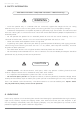
Warning
Take care, respect the polarity
and the maximum DC voltage.
An inverted polarity or a different
voltage could damage the device
or part of its component parts.
Please note that (-) and (+) pins of the amplifier must be connected to the same output channel.