KMT12/KMT18 USER’S MANUAL English
KMT12/KMT18 2 REV.
KMT12/KMT18 Contents SYMBOLS 5 1. INTRODUCTION 7 2. APPLICATIONS 7 3. KEY FEATURES 7 4. UNPACKING 8 5. WARRANTY 8 6. SAFETY 8 7. PHYSICAL 9 8. AMPLIFIER 11 8.1 AC POWER CONNECTOR 11 8.2 VOLTAGE REQUIREMENT 11 8.3 CURRENT REQUIREMENT 11 8.4 REAR PANEL 12 8.5 TOUCH SCREEN FUNCTIONS 14 8.6 AUDIO INPUT CONNECTOR WIRING 15 8.7 AMPLIFICATION AND PROTECTION CIRCUITRY 15 9. K-Framework 16 9.1 SYSTEM REQUIREMENTS 16 9.2 Installation and set up 16 9.
KMT12/KMT18 4 REV.
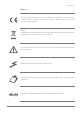
KMT12/KMT18 SYMBOLS K-array declares that this device is in compliance with applicable CE standards and regulations. Before putting the device into operation, please observe the respective country-specific regulations! WEEE Please dispose of this product at the end of its operational lifetime by bringing it to your local collection point or recycling center for such equipment. This symbol alerts the user to the presence of recommendations about the product’s use and maintenance.
KMT12/KMT18 6 REV.
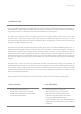
KMT12/KMT18 1. INTRODUCTION The K-array KMT12 and KMT18 are full-featured audio systems featuring a powered subwoofer, programmable onboard DSP and multiple analog and digital inputs and outputs for creating a wide array of speaker configurations. The KMT12 features a 12” subwoofer, while the KMT18 features an 18” subwoofer.
KMT12/KMT18 4. UNPACKING Each K-array loudspeaker is built to the highest standard and thoroughly inspected before leaving the factory. Upon arrival, carefully inspect the shipping carton, then examine and test your new loudspeaker. If you find any damage, immediately notify the shipping company. Only the consignee may institute a claim procedure regarding the system’s electronic equipment. 5.
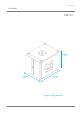
KMT12/KMT18 7. PHYSICAL KMT12 33.5 cm 13.19” 32.5 cm 12.91” 43.5 cm 17.13” weight: 15.6 kg (34.39 lbs) REV.
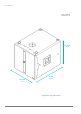
KMT12/KMT18 KMT18 47.5 cm 18.70” 61 cm 24.02” 46.5 cm 18.31” weight: 27.6 kg (60.85 lbs) 10 REV.
KMT12/KMT18 8. AMPLIFIER 8.1 AC POWER CONNECTOR The amplifier module and any audio equipment connected to it (mixing consoles, processors, etc.) must be properly connected to the AC power distribution, preserving AC line polarity. All grounding points should be connected to a single node or common point, using the same cable gauge as the neutral and line cables.
KMT12/KMT18 For best performance, voltage drops should not exceed 10% at 115V or 5% at 230V. The minimum electrical service amperage required by a K-array loudspeakers system is the sum of their maximum continuous RMS current. We recommend allowing an additional 30% above the minimum amperage to prevent peak voltage drops at the service entry. KMT12/KMT18 max continuous apparent power (VA) 410VA(>10 sec) - 2200VA (<1 sec) 8.4 REAR PANEL 14 20 1 6 4 2 5 9 11 12 13 15 19 3 7 16 8 10 17 18 19 12 REV.
KMT12/KMT18 1) CH1 Line Input. XLR line level input with +4 dBu sensitivity. 2) CH2 Mic/Line Input. XLR input, with selectable sensitivity for Mic (-30 dBu) or Line (+4 dBu). 3) CH1 Parallel Line Out. XLR parallel output, providing a direct signal from the CH1 Line Input. This output cannot be processed or controlled via the K-Framework software. 4) Phantom Power switch. Turns phantom power (48V) on/off on CH1 and CH2 inputs. 5) Mic/Line switch.
KMT12/KMT18 8.5 Touch screen functions HOME PAGE The main functions of the onboard DSP can be managed with the integrated touch screen. Functions are grouped into six pages, shown as icons on the Home page. To reach the Home page from any other page, touch the Home button. INPUT PAGE OUTPUT PAGE ROUTING PAGES The Input page allows users to independently manage the amplitude of all the four input channels.
KMT12/KMT18 DELAY PAGE The Delay page allows users to independently set the delays for the speaker system (Subwoofer and Speaker Out). This delay is summed with the delays from the Routing pages of Subwoofer and Speaker Out. The COARSE and FINE controls allow users to change the delay in larger and smaller steps. Notes: The delay control does not affect the XLR DSP out. Delay for this output line can only be managed through the K-Framework dedicated controls. 8.
KMT12/KMT18 9. K-Framework 9.1 System requirements SYSTEM REQUIREMENTS: Operating System: Windows XP / Vista / 7 CPU: Intel Pentium Dual Core Memory: 2 GB REQUIRED COMPONENTS: Microsoft .NET Framework 4: http://www.microsoft.com/download/en/details.aspx?id=17718 Microsoft Visual C++ 2010 Redistributable Package (x86): http://www.microsoft.com/download/en/details.aspx?id=5555 Microsoft Visual C++ 2010 Redistributable Package (x64): http://www.microsoft.com/download/en/details.aspx?id=14632 9.
KMT12/KMT18 4) When asked to allow the online search, select “Not now” and click “Next.” 5) When asked for the driver’s location, select “Install from a list or specific location.” 6) In the search and installation options window, select “Search for the best driver in this location” and check the “Include this location in the search” checkbox, then browse for the driver’s folder. The path should read: C:\ProgramFiles\K-array\K-framework\drivers_rev02 Select the new driver file and click “Next.
KMT12/KMT18 At startup K-Framework will show the following window: A5 A6 A3 A2 A1 A4 img. A A1) Connected Devices Indicator shows the number of detected connected devices. N.B.: At startup, the indicator will show 0 devices, even if one or more units are connected. To detect all connected devices, click the “Connect” button (A2). A2) Connect Button detects connected devices. A3) Demo Button activates the demo mode of K-Framework.
KMT12/KMT18 B1 B2 B3 img. B B1) Connected Device Name. B2) Device Menu Button shows and hides the device menu. B3) Device Menu displays the basic information about the device and the shortcuts to open all available Editing Tabs. 9.3 User Tabs: HOME img. C From the Home window, users can access the dedicated tabs, which follow the signal flow from input stage to output stage. REV.
KMT12/KMT18 INPUT TAB Allows users to independently manage the EQ and gain of the four input channels. D1 D3 D2 D4 D5 D6 D7 D8 img. D D1) Frequency response display. Shows the frequency response curve resulting from the filters set in the Input EQ window (below). D2) Input EQ window button. Opens the Input EQ window, where users can set three parametric filters for each input channel. D3) Input Volume buttons. Adjusts the amplitude of the input channel Input EQ window D4) Input Volume display.
KMT12/KMT18 ROUTING TAB E1) Routing switch button. When lighted, the signal coming from the corresponding input on the left column is routed to the corresponding output on the top row. E1 img. E DELAY TAB Allows users to independently manage the delay applied to the three output channels. F1 F2 F3 img. F F1) Global Delay buttons. Adjusts the amount of overall delay applied to both the subwoofer and speakon output (which can feed passive speakers, i.e.
KMT12/KMT18 OUTPUT TAB Allows users to independently manage the EQ, polarity, gain and limiting threshold of the three output channels. G3 G1 G4 G5 G2 G6 G11 G7 img. G G8 G9 G10 G1) Frequency response display. Show the frequency response curve resulting from the filters set in the Input EQ window. G2) Output EQ window button. Open the Output EQ window, where users can set up to six parametric filters for each output channel. G3) Phase button.
KMT12/KMT18 10. SERVICE To obtain service: 1) Contact the official K-array distributor in your country. Your local distributor will direct you to the appropriate service center. 2) If you are calling for service, please have the serial number(s) of the unit(s) available for reference. Ask for Customer Service, and be prepared to describe the problem clearly and completely. 3) If the problem cannot be resolved over the phone, you may be required to send the unit in for service.
KMT12/KMT18 11.
KMT12/KMT18 KMT18 Acoustics Speakers power handling 800 w Maximum power 1400 w 1 Impedance (EAS) Maximum SPL Coverage Omni Crossover Type Frequency Power Input Connectors Type Transducers 1 x 18” Neodymium speakers with 3” voice coil Audio Input Analog Connectors 2 male + 2 female 3-pin balanced XLR Digital Connectors 1 male + 1 female 3-pin XLR 1000 Watt 3 @8Ω Speaker power output 1000 Watt 3 @8Ω Protection Wiring I.
KMT12/KMT18 12. Declaration of conformity Manufacturer/Importer: K-array srl unipersonale Brand: K-ARRAY Address: via Paolina Romagnoli - 50037 S. Piero a Sieve Firenze ITALY Date of Issue: 10 / 01 / 2012 Model Code: KMT12 / KMT18 Declaration: Complies with essential protection requirements of Council Directive 89/336/EEC on the approximation of the Lows of the Member States relating to electromagnetic compatibility.
KMT12/KMT18 The contents of this manual are furnished for informational purposes only. Hp Sound Equipment s.r.l. assumes no responsibility for any errors or inaccuracies that may appear in this manual. Hp Sound Equipment s.r.l. reserves the right to make modifications without prior notice. REV.
UMC031AA01ENA K-array s.r.l. unipersonale Via Paolina Romagnoli - 50037 San Piero a Sieve (Firenze) - Italy tel. +39 055 8487222 - fax. +39 0558487238 e-mail: info@k-array.com www.k-array.