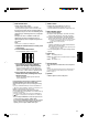
COLOR VIDEO MONITOR DEUTSCH INSTRUCTIONS ESPAÑOL ITALIANO FRANÇAIS TM-H150CG ENGLISH BEDIENUNGSANLEITUNG : FARB-VIDEO-MONITOR MANUEL D’INSTRUCTIONS : MONITEUR VIDEO COULEUR MANUALE DI ISTRUZIONI : MONITOR VIDEO A COLORI INSTRUCCIONES : MONITOR DE VIDEO A COLOR For Customer Use: Enter below the Serial No. which is located on the rear of the cabinet. Retain this information for future reference. Pour l’usage du client: Enter ci-dessous le numéro de série qui est situé sur l’arrière du coffret.
INSTRUCTIONS TM-H150CG Thank you for purchasing this JVC color video monitor. Before using it, read and follow all instructions carefully to take full advantage of the monitor’s capabilities. TM-H150CG_Cover.p65 5 04.1.
SAFETY PRECAUTIONS In order to prevent any fatal accidents caused by misoperation or mishandling the monitor, be fully aware of all the following precautions. WARNINGS To prevent fire or shock hazard, do not expose this monitor to rain or moisture. Dangerous high voltages are present inside the unit. Do not remove the back cover of the cabinet. When servicing the monitor, consult qualified service personnel. Never try to service it yourself. WARNING : THIS APPARATUS MUST BE EARTHED.
POWER CONNECTION The power supply voltage rating of this product is AC 120 V (For U.S.A. and Canada only) and AC 220 – 240 V (For European countries or United Kingdom), the power cord attached conforms to the following power supply voltage and countries. Use only the power cord designated to ensure Safety and EMC regulations of each countries. Power cord Power supply voltage : AC 120 V Countries : U.S.A.
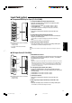
Controls and Features Front Panel 1 2 3 4 5 6 7 8 9 p q w 1 CHROMA ( : Chroma)/PHASE ( : Phase) button* Press this button to activate the Chroma (picture color density) adjustment mode or the Phase (picture hue) adjustment mode. Each time you press the button, the adjustment modes change. Chroma“Phase Adjust the value with the VOLUME/SELECT (– +) buttons while the level bar appears on the screen.
8 ASPECT button Displays only the blue signals. Changes the aspect ratio from 4:3 to 16:9. • The button lights while this function is activated. • Pressing the button again restores the normal screen. • The button lights while the aspect ratio is 16:9. • Pressing the button again returns the aspect ratio to 4:3. By using this function with the standard color-bar currently used, you can check if CHROMA (picture color density) or PHASE (picture hue) is adjusted properly. Also you can check if “COMPO.
Controls and Features (cont’d) Rear Panel e SLOT i REMOTE o r MAKE/ TRIGGER ; t POWER y a u e VIDEO A terminal u AUDIO B terminal Input (IN) and output (OUT) terminals for composite signals. Input (IN) and output (OUT) terminals for analog audio signals. • The IN and OUT terminals are bridge-connected (auto termination). • The IN and OUT terminals are bridge-connected (auto termination). NOTE: Use the AUDIO A terminals for the corresponding audio signals.
Input Card (option) 7 Component/RGB Input Card (IF-C01COMG) 1 Component/RGB signal input/output terminals Input (IN) and output (OUT) terminals for the component (color difference) or the RGB signal. G/ Y IN To select Component signal: Press the INPUT SELECT C button. To select RGB signal: Press the INPUT SELECT D button. • The IN and OUT terminals are bridge-connected (auto termination).
Controls and Features (cont’d) Input Card (option) (cont’d) 7 SDI Input Card (IF-C21SDG/IF-C51SDG) The EMBEDDED AUDIO signal is acceptable. (IF-C51SDG is also equipped with an AUDIO LEVEL METER function.) 1 SWITCHED OUT terminal SWITCHED OUT IN1 E.AUDIO SDI Output (OUT) terminal for the re-clocked signal. The input signal from the input terminal currently selected (IN1 or IN2) is re-clocked and output from this terminal.
Preparation Installing the Input Card 1 Turn off the main power switch on the rear panel of the monitor and unplug the AC power cord from the AC outlet. 2 Unscrew the screws and remove the slot cover from the input card slot on the rear panel of the monitor. SLOT REMOTE MAKE/ TRIGGER Slot cover Insert the input card’s circuit board (green-colored) into the slot, fitting the board to the guide rails on the top and bottom of the slot.
Basic Menu Operations (MENU, SET-UP MENU) 7 About the Menu Screens This monitor features MENU which contains the functions normally used and SET-UP MENU which contains the initial settings of the monitor. MENU Items Functions APERTURE Adjusts the picture aperture level. ADJ. BAR POSI. Selects the level bar position on the screen which appears when adjusting picture or volume. COLOR TEMP. Selects the color temperature. COLOR SYSTEM 1) Selects the color system. COMPO.
7 Displaying the menu screens To display MENU Press the MENU button on the front panel. To display SET-UP MENU Press the fi button while holding down the MENU button on the front panel. 7 Initializing the Settings You can initialize the following settings of the monitor: MENU, SET-UP MENU, picture adjustment, volume level 1 Press the stand-by button to turn off the monitor (on stand-by). 2 While holding down both the MENU button and the fi button, press the standby button to turn on the monitor.
How to Use MENU
How to Use SET-UP MENU Function and display of the button varies depending on the selected item. Buttons PICTURE SUB ADJ . H. POSITION : 00 V. POSITION : 00 WHITE BALANCE CONTROL LOCK : OFF STATUS DISPLAY : ON REMOTE SYSTEM : MAKE INPUT REMOTE : A-D EXIT Displays Functions fi ∞ Selects the items in forward rotation. % 5 Selects the items in reverse rotation. VOLUME/ + Increases the value (up to the maximum). SELECT(+) 3 Selects the setting (value) in forward rotation.
How to Use SET-UP MENU (cont’d) WHITE BALANCE CONTROL LOCK Adjusts the white balance. Prohibits the monitor operations except turning on/off the monitor and adjusting volume. The menu operations are also prohibited. • ON: Activates this function. • OFF: Deactivates this function. NOTE: You can adjust the items in “WHITE BALANCE” separately for each color temperature (6500 or 9300). Select the color temperature you want to adjust beforehand.
How to Use the External Control 7 About the External Control This monitor has the REMOTE (remote) terminal that is used for the operation by an external control. You can select the following control methods according to the setting of “REMOTE SYSTEM” in SET-UP MENU: • MAKE (make contact system): Controls the function by short-circuiting the corresponding pin terminal to the GND pin terminal, or disconnecting (opening) it. • TRG.
Troubleshooting Solutions to common problems related to your monitor are described here. If none of the solutions presented here solve the problem, unplug the monitor and consult a JVC-authorized dealer or service center for assistance. Problems No power supply Points to be checked Measures (Remedy) Reference pages Is the power plug loosened or disconnected? Firmly insert the power plug. Is the main power turned OFF? Turn the main power switch on. 6 Connect the signal cable firmly.
Irregular color Wrong picture position Points to be checked Measures (Remedy) Reference pages Is the monitor placed or moved close to a speaker or any other device incorporating a magnet? Has the position of the monitor been changed with the power on? Move the device away from the monitor and turn off the monitor. Wait at least 30 minutes, then turn on the monitor. Has the picture position been changed? Adjust “H. POSITION” or “V. POSITION” in SET-UP MENU.
Specifications MODEL TM-H150CG Type Color video monitor Color system PAL, NTSC (3.58) 39 cm (15") measured diagonally, 90° deflection, in-line gun, trio-dot type (phosphor dot-trio pitch 0.27 mm) Picture tube Width: 285.5 mm (11 3/16") Height: 214 mm (8 3/8") Diagonal: 356 mm (14") Effective screen size Scanning frequency H: 15.734 kHz (NTSC), 15.625 kHz (PAL) V: 59.
7 Dimensions Unit : mm (inch) • Asterisks (*) are used to indicate the screen dimensions. Front Side 360 (14 1/4) 418 (16 1/2) 1.5 (1/16) 407 (16 1/8) 3.5 (1/4) 3.5 (1/4) 164 (6 1/2) 224 (8 7/8)* 310 (12 1/4) 295.5 (11 3/4)* 308 (12 1/4) 60.2 (2 3/8) 238 (9 3/8) 20 7/8) ENGLISH ( 7 Acceptable Signal Formats ‡: Acceptable –: Not acceptable When an input card (not supplied) is installed IF-C01COMG IF-C01SDG IF-C21SDG IF-C51SDG Terminals on the rear of the monitor NTSC (3.
TM-H150CG COLOR VIDEO MONITOR VICTOR COMPANY OF JAPAN, LIMITED Printed in Thailand 0204MKH-MW-MT © 2004 VICTOR COMPANY OF JAPAN, LIMITED TM-H150CG_Cover.p65 2 04.1.