COLOR VIDEO MONITOR INSTRUCTIONS TM-A130SU For Customer Use: Enter below the Serial No. which is located on the rear of the cabinet. Retain this information for future reference. Model No. : – TM-A130SU TM-A130SU Serial No.
Thank you for purchasing this JVC color video monitor. Before using it, read and follow all instructions carefully to take full advantage of the monitor's capabilities. SAFETY PRECAUTIONS WARNING : FCC INFORMATION (U.S.A. only) TO PREVENT FIRE OR SHOCK HAZARDS, DO NOT EXPOSE THIS MONITOR TO RAIN OR MOISTURE. CAUTION: Changes or modification not approved by JVC could void the user's authority to operate the equipment. CAUTION : To reduce the risk of electric shock, do not remove cover.
CONTENTS SAFETY PRECAUTIONS .......................................................................................... 2 CONTROLS AND FEATURES ................................................................................... 4 HOW TO HANDLE BASIC OPERATIONS ................................................................ 6 HOW TO USE THE MENU FUNCTIONS ................................................................... 7 HOW TO INITIALIZE THE SETTING .......................................................
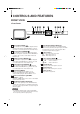
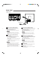
CONTROLS AND FEATURES FRONT VIEW – + B A ON OFF PHASE CHROMA BRIGHT CONTRAST MENU VOLUME/SELECT INPUT SELECT TM-A130SU – + B POWER A ON OFF PHASE CHROMA TM-A130SU BRIGHT CONTRAST MENU VOLUME/SELECT INPUT SELECT POWER 1 Phase button [PHASE 8 Input A button [INPUT SELECT A] ] Press this button to set the picture hue adjustment mode. Adjust the value with the VOLUME/SELECT 6 buttons. Also used as a control button in the menu function mode.
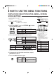
REAR VIEW VIDEO A IN OUT AUDIO B IN OUT A Y/C IN B IN OUT VIDEO A IN OUT AUDIO B IN OUT A Y/C IN B IN OUT To AC outlet (120 V AC, 50/60 Hz) 14 Video A terminals [VIDEO A IN/OUT] Video signal input (IN) and output (OUT) terminals. The output terminal is bridge-connected. IN : Video signal input terminal OUT : Bridge-connected video signal output terminal Notes: * For corresponding audio signals, use the AUDIO A terminals ^.
HOW TO HANDLE BASIC OPERATIONS BASIC OPERATION Color system indication (NTSC or PAL ) 1. Press the POWER switch to turn on the power. ON OFF ON : Power turns ON. (Power indicator: lit) OFF : Power turns OFF. (Power indicator: unlit) NTSC POWER 2. Press the INPUT SELECT button to choose input. B Selects video/audio signals input to terminals on the rear panel.
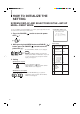
HOW TO USE THE MENU FUNCTIONS DISPLAY AND SELECTION IN THE
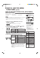
HOW TO USE THE MENU FUNCTIONS (cont'd) DISPLAY AND SELECTIONS IN THE MODE (SETTING) screen You can set the following set-up menu items. ● H. POSITION ● WHITE BALANCE ● CONTROL LOCK 1 ‰ H. POSITION : 00 WHITE BALANCE CONTROL LOCK : OFF Note: 3 ● Parameters for H. POSITION can be set separately depending on the video input (Input 2 A or Input B) selected by the input select buttons on the front panel.
Set-up menu items H. POSITION WHITE BALANCE DRIVE CUT OFF Purpose Settings Adjusts the horizontal position of the screen (+ : Horizontal position shifts to the right/–: Horizontal position shifts to the left) Adjusts the white balance –05 –04 •• –01 00 +01 •• +04 +05 Selects DRIVE (DRV) or CUT OFF (CUTO) adjustment. Screen setting is changed to the selected setting mode. Select R/G/B buttons corresponding to the function display to adjust. R.
HOW TO INITIALIZE THE SETTING SCREEN DISPLAY AND SELECTIONS IN THE RESET MODE You can set
BASIC CONNECTION EXAMPLE Notes: ● Before connecting your system, make sure that all units are turned off. ● The illustration below shows some examples of different connections. Terminal connections may differ depending on the component connected. Be sure to refer to the instructions provided with the unit(s) you are connecting. ● Each pair of input (IN) and output (OUT) terminals are bridge-connected. However, the Y/C input terminal (Y/C IN) has no output terminal (OUT) corresponding to it.
TROUBLESHOOTING Solutions to common problems related to your monitor are described here. If none of the solutions presented here solves the problem, unplug the monitor and consult a JVC-authorized dealer or service center for assistance. Problems Points to be checked Measures (Remedy) No power supply. Is the power plug loosened or disconnected? Firmly insert the power plug. No picture with the power on. Is the video signal output from the connected component? Set the connected component correctly.
SPECIFICATIONS MODEL TM-A130SU Color video monitor NTSC (3.58), PAL Type Color system Picture tube 13" measured diagonally, 90° deflection, in-line gun, vertical line trio type (phosphor stripe pitch 0.64 mm) Effective screen size Width Height Diagonal 11-1/8" (280.8 mm) 8-3/8" (210.6 mm) 13-1/4" (335.4 mm) Scanning frequency H : 15.734 kHz (NTSC), 15.625 kHz (PAL) V : 59.
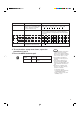
7 Dimensions Unit : Inch (mm) < Side View > < Front View > 14-5/8 (368.5) + B A ON OFF PHASE CHROMA BRIGHT CONTRAST MENU VOLUME/SELECT TM-A130SU INPUT SELECT POWER 2-5/8 (63.7) 11-1/4 (284) * Asterisks (∗) are used to indicate front panel dimensions. 7 Y/C (Mini DIN 4 pin) terminal specification Pin No. Y/C IN 14 4 3 2 1 1/4 (5) – 3/16 (3.5) * 11-3/8 (287) 12-1/4 (310) 8-5/8 (217) * 14-3/8 (363.5) 1/16 (1.
TM-A130SU COLOR VIDEO MONITOR JVC PROFESSIONAL PRODUCTS COMPANY DIVISION OF US JVC CORP. 1700 Vallery Road Wayne, NJ07470 JVC CANADA INC.