
Computer Monitor User Manual

10
Controls and Features (cont.)
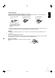
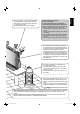
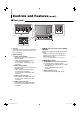
7 Rear panel
1 AC inlet
Power input connector. Connect the provided AC
power cord to an AC outlet (AC 120 V/AC 220 –
240 V, 50 Hz/60 Hz).
2 VIDEO terminals
a VIDEO 1 terminals (BNC)
Input (IN) and output (OUT) terminals for the
composite signals.
• The IN and OUT terminals are bridge-
connected (auto termination).
• Use the AUDIO 1 terminal for the audio
connection.
b VIDEO 2 terminals (BNC)
Input (IN) and output (OUT) terminals for the
composite signals.
• The IN and OUT terminals are bridge-
connected (auto termination).
• Use the AUDIO 2 terminal for the audio
connection.
c AUDIO 1 terminal (pin jack)
Input terminal for the analog audio signals.
• Use the VIDEO 1 terminal for the video
connection.
d AUDIO 2 terminal (pin jack)
Input terminal for the analog audio signals.
• Use the VIDEO 2 terminal for the video
connection.
3 REMOTE (external control) terminal (MAKE/
TRIGGER)
Ter minals for controlling the monitor by an external
control.
• Enables the monitor to be controlled by short-
circuiting the pin terminal in this terminal or by
inputting the pulse signal.
☞ “How to Use the External Control” on page 18
4 COMPONENT terminals
e COMPONENT terminal (mini D-sub 15-pin)
Input terminal for the component signals.
• This terminal is not compatible with PC signals
and RGB signals.
• Use the supplied conversion cable for
connection.
f AUDIO terminal (pin jack)
Input terminal for the analog audio signals.
e
c
dba
3
2
4
f
03_TM-15L1D-EN2.indd 1003_TM-15L1D-EN2.indd 10 06.11.15 1:07:35 PM06.11.15 1:07:35 PM