TK-C1480, TK-C1481 COLOUR VIDEO CAMERA COLOUR VIDEO CAMERA TK-C1480 TK-C1481 INSTRUCTIONS ∞ C AM DEO R VI COLO BF LO ER A OK L DIGITA For Customer Use: Enter below the Serial No. which is located on the body. Retain this information for future reference. VICTOR COMPANY OF JAPAN, LIMITED ® ® is a registered trademark owned by VICTOR COMPANY OF JAPAN, LTD. is a registered trademark in Japan, the U.S.A., the U.K. and many other countries. © 2001 VICTOR COMPANY OF JAPAN, LIMITED Model No.
IMPORTANT SAFEGUARDS 1. 2. 3. 4. Read all of these instructions. Save these instructions for later use. All warnings on the product and in the operating instructions should be adhered to. Unplug this appliance system from the wall outlet before cleaning. Do not use liquid cleaners or aerosol cleaners. Use a damp cloth for cleaning. 5. Do not use attachments not recommended by the appliance manufacturer as they may cause hazards. 6.
Safety Precautions FOR USA AND CANADA Due to design modifications, data given in this instruction book are subject to possible change without prior notice. CAUTION RISK OF ELECTRIC SHOCK DO NOT OPEN CAUTION:TO REDUCE THE RISK OF ELECTRIC SHOCK. DO NOT REMOVE COVER (OR BACK). NO USER-SERVICEABLE PARTS INSIDE.REFER SERVICING TO QUALIFIED SERVICE PERSONNEL.
INTRODUCTION Operating Precautions Features A new DSP (Digital Signal Processor) features a Extended Dynamic Range (ExDR) and enables to shoot both bright and dark locations. The use of a new CCD with a SENSE UP (X32) function realized the minimum luminous flux density for subject of 0.8 lx (F1.2, 50%, AGC 20dB) and 0.025 lx (at slow shutter). A motion detector function detects the motion inside an image and emits alarm signals.
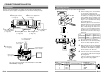
INTRODUCTION Controls, Connectors and Indicators ! @# 2 1 3 $ SET 4 AWC CAMERA SETUP MENU 5 ON LL SIMPLEX ON EXT TERM-OFF INT/GL DUPLEX RX TERM-OFF NOT USED VIDEO DC 7 This means to attach the lens. This is applicable to both the C-mount lenses and CS-mount lenses. 2 Backfocus adjustment ring Adjusting the back focus during lens installation. When readjustment is required, loosen the locking screw 3 by turning it counterclockwise and turn the back focus adjustment ring 2 .
INTRODUCTION Controls, Connectors and Indicators (Continued) Switch of External Synchronization Signal This is a terminating ON/OFF switch for the external synchronization input signal. When this is switched ON, termination is executed via a 75 Ω resistor. ON: terminates at 75Ω. OFF: does not terminate at 75Ω. (ON: At time of factory shipment) 15 [INT/GL, LL] Selector Switch for Synchronizing System This switch can set a synchronizing system of the camera.
CONNECTION/INSTALLATION RM-P2580 System Connecting the control signal cable System with up to 8 cameras H Av Pk L Camera 2 Control signal cable Power cable Camera TK-C1480 AC24V or DC12V ALC LEVEL MACHINE ID:1 (Menu screen) RX TERM: OFF (switch) (Use a twisted-pair cable for connection. Page 17.
CONNECTION/INSTALLATION Mounting the lens Procedures Execute connection/installation according to the procedures described below. Turn OFF the power supply to all equipment to be used before making carefully. 4.Setting the switches Mount the lens according to the procedures described below. 1. 6.Back focus adjustment ( Page 13) ( Page 21) SET CAMERA SETUP BF CK (b) VIDEO DC F 5.Lens adjustment 7.
CONNECTION/INSTALLATION Connections on the back Power supply - 1 2 CLASS 2 ONLY(U TYPE) ISOLATED POWER ONLY (E TYPE) + AC24V DC12V TK-C1480U and TK-C1480E (DC 12 V or 24 V) TX+ TX- RX+ RX- AUX GND A B C D Y/C OUT SYNC IN VIDEO OUT Connect the DC 12 V or the AC 24 V power supply to the DC 12V/AC 24V terminals. To prevent connection errors or a cable disconnection, we recommend the use of lug plates for the connections.
CONNECTION/INSTALLATION Mounting the camera When mounting the camera on a fixer, pan/ tilt, etc., use the camera mounting screw hole located on the camera-mounting bracket. Camera mounting screw Camera-mounting bracket CAUTION: Use the screw with a length shorter than 7mm from a camera-mounting face. q IRIS VIDEO DC MAX. 7mm Furthermore, make use of the rotation prevention hole to prevent the camera from falling and securely mount the camera.
CONNECTION/INSTALLATION Back focus adjustment Lens adjustment Connect the camera according to the connection method, turn it on, display an image on the monitor, and check the image. The camera has been factory-adjusted to the best position, but it may need to be adjusted according to the object conditions or combination of lenses. If the image is unnatural, adjust it as follows: (Also read the instruction manual of the lens.) H Av Pk L ALC LEVEL LEVEL adjustment ALC adjustment (Does not operate.
CONNECTION/INSTALLATION MENU SETTING Auto white balance control adjustment Setting the menu Each light source has its own colour temperature. Therefore, when the main light source lighting an object is changed, the white balance should be adjusted again by pressing the AWC button. 1. AWC button SET AWC MENU CAMERA SETUP EXT TERM-OFF ON LL SIMPLEX ON INT/GL DUPLEX RX TERM-OFF When the AWC button is pressed for approx. one sec., the white balance is adjusted for the object being recorded. 3.
MENU SETTING The flow of menu screen Page 26 MENU S YNC A DJ UST . . A L C S E T T I NGS . . V I DEO A DJ UST . . MODE S E L ECT . . MOT I ON D E T E CT . . COMMUN I CAT I ON . . F A C TORY SET T I NGS . . SHUT TE R ( E x DR ) SYNC A D J US T V PHASE H PHASE S C COARS E S C F I NE S HUT T ER SPEED F AST L I M I T E x D R L EV E L M .
MENU SETTING SYNC ADJUST Screen This executes the setting regarding synchronization. Item Functions and set values Item Initial value V PHASE This adjusts the vertical synchronization to those of other cameras when a selector switch for the synchronizing system on the side is at LL. (50Hz (60Hz) power region only. ( ): TK-C1480U) When it is not set to LL, “---” will appear, disabling change the set value.
MENU SETTING ALC SETTINGS Screen (Continued) Item Functions and set values FAST LIMIT This sets the fastest value of a shutter speed when AUTO is set. The MANUAL, M. ExDR, A. ExDR set value is displayed as “- - -” and cannot be changed. The higher the shutter speed becomes, the more smear phenomenon is emphasized, which is peculiar to the CCD.
MENU SETTING VIDEO ADJUST Screen MODE SELECT Screen Adjustments are made on video signals. Item WHITE BALANCE Functions and set values Selects the white balance adjustment function. The white balance can be adjusted manually or automatically for light within the colour temperature range of 2500K to 8000K. • ATW: Auto-Tracking White Balance mode. This automatically adjusts the white balance. • AWC: Auto White Balance Controll mode. When the SET button is pressed, the adjustment screen appears.
MENU SETTING MOTION DETECT Screen(Continued) Item LEVEL AREA EDIT ALARM TIME Functions and set values COMMUNICATION Screen Initial value This sets the level that detects motion. If the item MODE is set to OFF, “- - -” will appear, and settings cannot be changed. To function with large signal level change…decrease the value To function with small signal level change…increase the value [Set values: –5 to NORMAL to 5] NORMAL This sets the range in which the motion detecting function works.
MENU SETTING BLC EDITTING Screen Manual Adjustment of White Balance It is possible to set freely the light metering area for backlight compensation. The 2 screens of EDIT1 and EDIT2 can be set. MENU button SET button A L C SE T T I NGS I R I S L E VE L A V E RAGE : P EAK S H UT T ER ( E x DR ) A G C MODE S E NS E U P P R I OR I T Y B LC When automatic adjustment of the white balance results in a “reddish screen”, etc., adjust the white balance manually.
MENU SETTING CAMERA TITLE Setting Setting the MOTION DETECT Function Up to 24 characters can be selected as camera text for each camera. The set characters are displayed at the bottom of the screen. MENU button SET button 1. Then, the CAMERA TITLE screen is brought up. SET AWC CAMERA SETUP MENU Select the item CAMERA TITLE on the MODE SELECT screen, and push the SET button. 2. Select the first character from the character area using buttons.
OTHERS Installing the ferrite core To retain electromagnetic compatibility, use the ferrite cores provided when connecting to the lens or the power source. Video-iris lens (or galvanometnc-iris lens) Wind twice H ALC LEVEL Av Pk L IRIS VIDEO DC Ferrite core Notes: DIMENSIONS (Unit: mm) 70 U1-32 149 138 5 4-R 35 55 63 39 42 71 1/4-20UNC .. geprufte Sicherheit SS412174H-002 SC46171H-001 .. -NE PAS OUVRIR. Specifications TUV Rheinland Product Safety WARNING: SHOCK HAZARD -DO NOT OPEN.