TK-C1460B COLOUR VIDEO CAMERA COLOUR VIDEO CAMERA TK-C1460B INSTRUCTIONS ERA DEO R VI COLO CAM OK BF LO L DIGITA VICTOR COMPANY OF JAPAN, LIMITED ® ® is a registered trademark owned by VICTOR COMPANY OF JAPAN, LTD. is a registered trademark in Japan, the U.S.A., the U.K. and many other countries. © 2002 VICTOR COMPANY OF JAPAN, LIMITED Printed in Japan LWT0066 This instruction manual is made from 100% recycled paper.
IMPORTANT SAFEGUARDS 1. 2. 3. 4. Read all of these instructions. Save these instructions for later use. All warnings on the product and in the operating instructions should be adhered to. Unplug this appliance system from the wall outlet before cleaning. Do not use liquid cleaners or aerosol cleaners. Use a damp cloth for cleaning. 5. Do not use attachments not recommended by the appliance manufacturer as they may cause hazards. 6.
Safety Precautions Due to design modifications, data given in this instruction book are subject to possible change without prior notice. Thank you for purchasing this product. (These instructions are for TK-C1460BE) Before beginning to operate this unit, please read the instruction manual carefully in order to make sure that the best possible performance is obtained. CONTENTS WARNING: TO REDUCE THE RISK OF FIRE OR ELECTRIC SHOCK, DO NOT EXPOSE THIS APPLIANCE TO RAIN OR MOISTURE. INTRODUCTION Features ...
INTRODUCTION Operating Precautions Features A new DSP (Digital Signal Processor) features a Extended Dynamic Range (ExDR) and enables to shoot both bright and dark locations. The use of a new CCD with a SENSE UP (X32) function realized the minimum luminous flux density for subject of 0.6 lx (F1.2, 50%, AGC 20dB) and 0.019 lx (at SENSE UP (X32)). Furthermore, we realized 0.02 lx (F1.2, 50% AGC 20dB) thanks to the function of B/W mode.
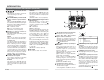
INTRODUCTION Controls, Connectors and Indicators SET AWC CAMERA SETUP ON LL SIMPLEX ON EXT TERM-OFF INT/GL DUPLEX RX TERM-OFF MENU NOT USED VIDEO DC 1 Lens mount To attach the lens. This is applicable to both C-mount lenses and CS-mount lenses. 2 Back focus adjustment ring Adjusting the back focus during lens installation. When readjustment is required, loosen the locking screw 3 by turning it counterclockwise and turn the back focus adjustment ring 2 .
INTRODUCTION Controls, Connectors and Indicators (Continued) Switch of External Synchronization Signal This is a terminating ON/OFF switch for the external synchronization input signal. When this is switched ON, termination is executed via a 75 Ω resistor. ON: terminates at 75Ω. OFF: does not terminate at 75Ω. (ON: At time of factory shipment) 15 [INT/GL, LL] Selector Switch for Synchronizing System This switch sets the synchronizing system for the camera.
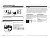
CONNECTION/INSTALLATION RM-P2580 System System with up to 8 cameras H Av Pk L Camera 2 Control signal cable Camera TK-C1460B Power cable AC24V or DC12V ALC LEVEL MACHINE ID:1 (Menu screen) RX TERM: OFF (switch) (Use a twisted-pair cable for connection. Page 17.
CONNECTION/INSTALLATION Procedures Mounting the lens Execute connection/installation according to the procedures described below. Turn OFF the power supply to all equipment to be used before making carefully. 4.Setting the switches Mount the lens according to the procedures described below. 1. 6.Back focus adjustment ( Page 13) ( Page 21) SET CAMERA SETUP CK (b) VIDEO DC F 5.Lens adjustment 7.
CONNECTION/INSTALLATION Installing the ferrite core To retain electromagnetic compatibility, use the ferrite cores provided when connecting to the lens. Video-iris lens (or galvanometnc-iris lens) H ALC LEVEL Av Pk L IRIS VIDEO DC Ferrite core Wire clamp Notes: Install the ferrite cores within 50 mm of the camera-side connectors. (Fasten the ferrite core with the wire clamp provided.
CONNECTION/INSTALLATION Mounting the camera When mounting the camera on a fixer, pan/ tilt, etc., use the camera mounting screw hole located on the camera-mounting bracket. Camera mounting screw hole Camera-mounting bracket CAUTION: Use the screw with a length shorter than 7mm from a camera-mounting face. q IRIS VIDEO DC MAX. 7mm Furthermore, make use of the rotation prevention hole to prevent the camera from falling and securely mount the camera.
CONNECTION/INSTALLATION Lens adjustment Back focus adjustment Connect the camera according to the connection method, turn it on, display an image on the monitor, and check the image. The camera has been factory-adjusted to the best position, but it may need to be adjusted according to the object conditions or combination of lenses. If the image is unnatural, adjust it as follows: (Also read the instruction manual of the lens.) H Av Pk L ALC LEVEL LEVEL adjustment ALC adjustment (Does not operate.
CONNECTION/INSTALLATION MENU SETTING Auto white balance control adjustment Setting the menu Each light source has its own colour temperature. Therefore, when the main light source lighting an object is changed, the white balance should be adjusted again by pressing the AWC button. 1. AWC button SET AWC MENU CAMERA SETUP EXT TERM-OFF ON LL SIMPLEX ON INT/GL DUPLEX RX TERM-OFF When the AWC button is pressed for approx. one sec., the white balance is adjusted for the object being recorded. 3.
MENU SETTING The flow of menu screen Page 26 MENU S YNC A DJ UST . . A L C S E T T I NGS . . V I DEO A DJ UST . . MODE S E L ECT . . MOT I ON D E T E CT . . COMMUN I CAT I ON . . MA I NT E NA NCE . . F A C TORY SET T I NGS . . Page 27 SHUT TE R / E x DR SYNC A D J US T V PHASE H PHASE S C COARS E S C F I NE S HUT T ER SPEED F AST L I M I T E x D R L EV E L M .
MENU SETTING SYNC ADJUST Screen This executes the setting regarding synchronization. Item Functions and set values Item Initial value V PHASE This adjusts the vertical synchronization to those of other cameras when a selector switch for the synchronizing system on the side is at LL. (50Hz power region only.) When it is not set to LL, “---” will appear, disabling change the set value.
MENU SETTING ALC SETTINGS Screen (Continued) Item Functions and set values Initial value FAST LIMIT This sets the fastest value of a shutter speed when AUTO is set. The MANUAL, M. ExDR, A. ExDR set value is displayed as “- - -” and cannot be changed. The higher the shutter speed becomes, the more smear phenomenon is emphasized, which is peculiar to the CCD.
MENU SETTING ALC SETTINGS Screen (Continued) Item Functions and set values VIDEO ADJUST Screen Initial value Item B&W COLOUR This function sets the colour modes to colour or B&W. When switching the mode between “colour’’ and “B&W” MODE .. is carried out, the focus may be dislocated. In such a case adjust the focus again. B&W LEVEL E-30 Adjustments are made on video signals. Switches the mode from colour to B&W and visa-versa. OFF : Turns the B&W mode switching function off.
MENU SETTING MODE SELECT Screen Titles, image reversion, etc., are set. Item Functions and set values Initial value CAMERA TITLE EDIT Bring up the CAMERA TITLE, EDIT screen. ( Page 38) REVERSE MODE Settings are executed for image reversion. OFF: Image does not reverse. R-L: Left and right of the image are reversed. U-D: Up and down of the image are reversed. ALL: Up and down and left and right of the image are reversed.
MENU SETTING COMMUNICATION Screen MOTION DETECT Screen Settings are executed about the motion detecting function that emits alarm signals when there exists any motion in the image. Alarm signals are output from the auxiliary terminals on the back. Item Functions and set values Initial value MODE This sets ON/OFF of motion detecting function. OFF: Motion detecting function does not work. ON: Motion detecting function works. LEVEL This sets the level that detects motion.
MENU SETTING BLC EDITTING Screen Manual Adjustment of White Balance It is possible to set freely the light metering area for backlight compensation. The 2 screens of EDIT1 and EDIT2 can be set. MENU button SET button A L C SE T T I NGS I R I S L E VE L A V E RAGE : P EAK S H UT T ER / E x DR A G C MODE L O L U X MO D E S E NS E U P P R I OR I T Y B LC B&W/COLOUR MODE When automatic adjustment of the white balance results in a “reddish screen”, etc., adjust the white balance manually.
MENU SETTING CAMERA TITLE Setting Setting the MOTION DETECT Function Up to 24 characters can be selected as camera text for each camera. The set characters are displayed at the bottom of the screen. MENU button SET button 1. Then, the CAMERA TITLE screen is brought up. SET AWC CAMERA SETUP MENU Select the item CAMERA TITLE on the MODE SELECT screen, and push the SET button. 2. Select the first character from the character area using buttons.
Output of Black-White/Color switching signal It is possible to output black-white/color switching signal from the AUX terminal on the back of this unit. Perform the following settings. Control by Black-White/Color switching signal from the outside Carry out the following setting when you link in motion the black-white/color switching of this unit and infrared illumination, etc., using the switching signal from the outside control device. Infrared illumination, etc.
OTHERS White spot compensation Specifications CCDs have the general characteristic that white spots appear on the screen when the CCD is operated at high temperatures or when they are used with a slow shutter speed. This unit has a built-in white spot compensation function to reduce these white spots. (The number and the size of the white spots changes according to the use temperature, the shutter speed, etc. Furthermore, there is a limit on the number of white spots that can be compensated.
BTK-C1480B, TK-C1481B COLOUR VIDEO CAMERA COLOUR VIDEO CAMERA TK-C1480B TK-C1481B INSTRUCTIONS ∞ COLO DEO R VI ERA CAM OK BF LO L DIGITA VICTOR COMPANY OF JAPAN, LIMITED ® ® is a registered trademark owned by VICTOR COMPANY OF JAPAN, LTD. is a registered trademark in Japan, the U.S.A., the U.K. and many other countries. © 2002 VICTOR COMPANY OF JAPAN, LIMITED Printed in Japan LWT0064 This instruction manual is made from 100% recycled paper.
IMPORTANT SAFEGUARDS 1. 2. 3. 4. Read all of these instructions. Save these instructions for later use. All warnings on the product and in the operating instructions should be adhered to. Unplug this appliance system from the wall outlet before cleaning. Do not use liquid cleaners or aerosol cleaners. Use a damp cloth for cleaning. 5. Do not use attachments not recommended by the appliance manufacturer as they may cause hazards. 6.
Safety Precautions Due to design modifications, data given in this instruction book are subject to possible change without prior notice. Thank you for purchasing this product. (These instructions are for TK-C1480BE and TK-C1481BEG) Before beginning to operate this unit, please read the instruction manual carefully in order to make sure that the best possible performance is obtained. CONTENTS WARNING: TO REDUCE THE RISK OF FIRE OR ELECTRIC SHOCK, DO NOT EXPOSE THIS APPLIANCE TO RAIN OR MOISTURE.
INTRODUCTION Operating Precautions Features A new DSP (Digital Signal Processor) features a Extended Dynamic Range (ExDR) and enables to shoot both bright and dark locations. The use of a new CCD with a SENSE UP (X32) function realized the minimum luminous flux density for subject of 0.6 lx (F1.2, 50%, AGC 20dB) and 0.019 lx (at slow shutter). A motion detector function detects the motion inside an image and emits alarm signals.
INTRODUCTION Controls, Connectors and Indicators SET AWC CAMERA SETUP MENU ON LL SIMPLEX ON EXT TERM-OFF INT/GL DUPLEX RX TERM-OFF NOT USED VIDEO DC 1 Lens mount To attach the lens. This is applicable to both C-mount lenses and CS-mount lenses. 2 Backfocus adjustment ring Adjusting the back focus during lens installation. When readjustment is required, loosen the locking screw 3 by turning it counterclockwise and turn the back focus adjustment ring 2 .
INTRODUCTION Controls, Connectors and Indicators (Continued) 15 [INT/GL, LL] Selector Switch for Synchronizing System This switch sets the synchronizing system for the camera. INT/GL: This is set for internal synchronization (INT) or external synchronization (GL). LL (Line Lock): The camera’s vertical synchronization is locked to the AC 24V power line frequency.
CONNECTION/INSTALLATION RM-P2580 System System with up to 8 cameras H Av Pk L Camera 2 Control signal cable Camera TK-C1480B Power cable AC24V or DC12V ALC LEVEL MACHINE ID:1 (Menu screen) RX TERM: OFF (switch) (Use a twisted-pair cable for connection. Page 17.
CONNECTION/INSTALLATION Procedures Mounting the lens Execute connection/installation according to the procedures described below. Turn OFF the power supply to all equipment to be used before making carefully. 4.Setting the switches Mount the lens according to the procedures described below. 1. 6.Back focus adjustment ( Page 13) ( Page 21) SET CAMERA SETUP BF VIDEO DC CK (b) F 5.Lens adjustment 7.
CONNECTION/INSTALLATION Installing the ferrite core To retain electromagnetic compatibility, use the ferrite cores provided when connecting to the lens. Video-iris lens (or galvanometnc-iris lens) Av Pk L H ALC LEVEL IRIS VIDEO DC MEMO • If thin cables are used (i.e. with a high resistance), a significant voltage drop will occur when the unit is at its maximum power consumption.
CONNECTION/INSTALLATION Mounting the camera When mounting the camera on a fixer, pan/ tilt, etc., use the camera mounting screw hole located on the camera-mounting bracket. Camera mounting screw Camera-mounting bracket CAUTION: Use the screw with a length shorter than 7mm from a camera-mounting face. q IRIS VIDEO DC MAX. 7mm Furthermore, make use of the rotation prevention hole to prevent the camera from falling and securely mount the camera.
CONNECTION/INSTALLATION Lens adjustment Back focus adjustment Connect the camera according to the connection method, turn it on, display an image on the monitor, and check the image. The camera has been factory-adjusted to the best position, but it may need to be adjusted according to the object conditions or combination of lenses. If the image is unnatural, adjust it as follows: (Also read the instruction manual of the lens.) H Av Pk L ALC LEVEL LEVEL adjustment ALC adjustment (Does not operate.
CONNECTION/INSTALLATION MENU SETTING Auto white balance control adjustment Setting the menu Each light source has its own colour temperature. Therefore, when the main light source lighting an object is changed, the white balance should be adjusted again by pressing the AWC button. 1. AWC button SET AWC MENU CAMERA SETUP EXT TERM-OFF ON LL SIMPLEX ON INT/GL DUPLEX RX TERM-OFF When the AWC button is pressed for approx. one sec., the white balance is adjusted for the object being recorded. 3.
MENU SETTING The flow of menu screen Page 27 Page 26 MENU S YNC A DJ UST . . A L C S E T T I NGS . . V I DEO A DJ UST . . MODE S E L ECT . . MOT I ON D E T E CT . . COMMUN I CAT I ON . . MA I N TE N A N CE . . F A C TORY SET T I NGS . . SHUT TE R / E x DR SYNC A D J US T V PHASE H PHASE S C COARS E S C F I NE S HUT T ER SPEED F AST L I M I T E x D R L EV E L M .
MENU SETTING SYNC ADJUST Screen This executes the setting regarding synchronization. Item Functions and set values Item Initial value V PHASE This adjusts the vertical synchronization to those of other cameras when a selector switch for the synchronizing system on the side is at LL. (50Hz power region only.) When it is not set to LL, “---” will appear, disabling change the set value.
MENU SETTING ALC SETTINGS Screen (Continued) Item Functions and set values Initial value FAST LIMIT This sets the fastest value of a shutter speed when AUTO is set. The MANUAL, M. ExDR, A. ExDR set value is displayed as “- - -” and cannot be changed. The higher the shutter speed becomes, the more smear phenomenon is emphasized, which is peculiar to the CCD.
MENU SETTING VIDEO ADJUST Screen MODE SELECT Screen Adjustments are made on video signals. Item WHITE BALANCE Functions and set values Selects the white balance adjustment function. The white balance can be adjusted manually or automatically for light within the colour temperature range of 2500K to 8000K. • ATW: Auto-Tracking White Balance mode. This automatically adjusts the white balance. • AWC: Auto White Balance Controll mode. When the SET button is pressed, the adjustment screen appears.
MENU SETTING MOTION DETECT Screen COMMUNICATION Screen Settings are executed about the motion detecting function that emits alarm signals when there exists any motion in the image. Alarm signals are output from the auxiliary terminals on the back. Item Functions and set values Initial value MODE This sets ON/OFF of motion detecting function. OFF: Motion detecting function does not work. ON: Motion detecting function works. LEVEL This sets the level that detects motion.
MENU SETTING BLC EDITTING Screen Manual Adjustment of White Balance It is possible to set freely the light metering area for backlight compensation. The 2 screens of EDIT1 and EDIT2 can be set. MENU button SET button A L C SE T T I NGS I R I S L E VE L A V E RAGE : P EAK S H UT T ER / E x D R A G C MODE S U P E R L O L UX S E NS E U P P R I OR I T Y B LC When automatic adjustment of the white balance results in a “reddish screen”, etc., adjust the white balance manually.
MENU SETTING CAMERA TITLE Setting Setting the MOTION DETECT Function Up to 24 characters can be selected as camera text for each camera. The set characters are displayed at the bottom of the screen. MENU button SET button 1. Then, the CAMERA TITLE screen is brought up. SET AWC CAMERA SETUP MENU Select the item CAMERA TITLE on the MODE SELECT screen, and push the SET button. 2. Select the first character from the character area using buttons.
OTHERS Specifications • Confirm that the cursor (>) is at the item CCD SPOT. C CD S P OT 3. heat up 30min in advance need Lens–cap to execute Press the SET button. • The CCD SPOT screen will be displayed. • If you do not want to perform white spot compensation, move the cursor (>) to CANCEL and press the SET button. C ANC E L E X E CU TE 4. Move the cursor (>) to EXECUTE. 5. Press the SET button. DIMENSIONS (Unit: mm) 70 U1-32 39 7. 35 42 71 1/4-20UNC Press the MENU button.