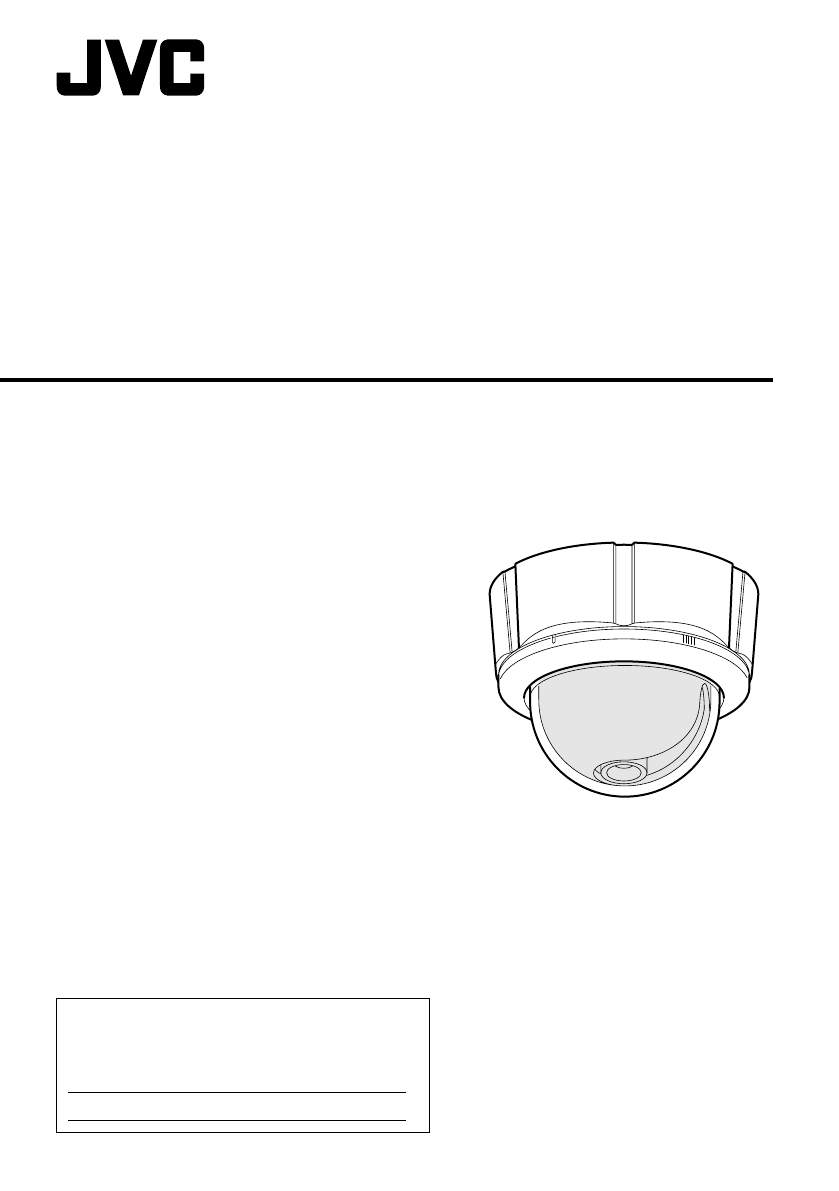
TK-C215V4_EN.book Page 1 Wednesday, June 14, 2006 8:00 PM DOME CAMERA TK-C215V4 INSTRUCTIONS (A) For Customer Use: Enter below the Serial No. which is located on the body. Retain this information for future reference. Model No. Serial No.
TK-C215V4_EN.book Page 2 Wednesday, June 14, 2006 8:00 PM Introduction Safety Precautions Information for Users on Disposal of Old Equipment [European Union] Attention: This symbol is only valid in the European Union. This symbol indicates that the electrical and electronic equipment should not be disposed as general household waste at its end-of-life.
TK-C215V4_EN.book Page 3 Wednesday, June 14, 2006 8:00 PM I INFORMATION FOR USA 䡵 INFORMATION This equipment has been tested and found to comply with the limits for a Class B digital device, pursuant to Part 15 of the FCC Rules. These limits are designed to provide reasonable protection against harmful interference in a residential installation.
TK-C215V4_EN.book Page 4 Wednesday, June 14, 2006 8:00 PM Introduction These are general IMPORTANT SAFEGUARDS and certain items may not apply to all appliances. IMPORTANT SAFEGUARDS 1. 2. 3. 4. Read all of these instructions. Save these instructions for later use. All warnings on the product and in the operating instructions should be adhered to. Unplug this appliance system from the wall outlet before cleaning. Do not use liquid cleaners or aerosol cleaners. Use a damp cloth for cleaning. 5.
TK-C215V4_EN.book Page 5 Wednesday, June 14, 2006 8:00 PM Thank you for purchasing this product. (These instructions are for: TK-C215V4U.) Before beginning to operate this unit, please read the instruction manual carefully in order to make sure that the best possible performance is obtained. Characteristics 䡵 Realizing a High Picture Quality This camera realizes 540 TV lines and S/N50 dB by employing a highly sensitive CCD with 380,000 pixels and a high-resolution video processing circuit.
TK-C215V4_EN.book Page 6 Wednesday, June 14, 2006 8:00 PM Introduction Contents Introduction Safety Precautions ......................................... 2 Characteristics ............................................... 5 Contents ......................................................... 6 Operating Precautions ................................... 7 Name of Parts ................................................ 8 Camera ....................................................... 8 Camera (Interior) ...........
TK-C215V4_EN.book Page 7 Wednesday, June 14, 2006 8:00 PM Operating Precautions 䢇 To save energy, when it is not being used turn the system’s power off. 䢇 This camera has been designed for indoor use. It cannot be used outdoors. 䢇 Do not install or use the camera in the following places. ● In a place exposed to rain or moisture. ● In a place with vapor or oil soot, for example in a kitchen. ● In a temperature outside the operating temperature range (-10 f to 50 f).
TK-C215V4_EN.book Page 8 Wednesday, June 14, 2006 8:00 PM Introduction Name of Parts Camera I H G B A F B C A B D E A Mounting hole (elliptical) x 4 Use these when mounting the camera to the electrical box. (A pg. 18) NOTE: When installing the camera onto the electric box, install it using the supplied adaptor ring. B Mounting hole (round) x 4 Use these when mounting the camera to the ceiling or wall. (A pg.
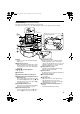
TK-C215V4_EN.book Page 9 Wednesday, June 14, 2006 8:00 PM Camera (Interior) The dome cover, inner dome and outer case are removed. Procedures for removal. (A pg. 14 AEmbedding the camera to the ceilingB, Step 3. to Step 5.) V Lens (A Next page) J K L M U T S Camera Unit (Rear) W O R Q P O N J Strap R Pan fastening Screw A plate to connect the camera unit and the dome cover. K Fastening Screw (x 3) When embedding the camera in the ceiling, turn this screw to secure the camera.
TK-C215V4_EN.book Page 10 Wednesday, June 14, 2006 8:00 PM Introduction A [RESET/SPOT] RESET/SPOT button Setting the Lens and Switches Set the video setting switches on the camera unit before mounting it. To set the switches, use a fine-tipped screwdriver. A RESET/ [SPOT] B R B LL PHASE C 1 2 3 4 5 6 7 8 D E O N 2 4 WHT. BAL. L IRIS LEVEL H FOCUS ADJUST When this button is pressed, the value of the white balance or phase adjusted manually is reset to the default value.
TK-C215V4_EN.book Page 11 Wednesday, June 14, 2006 8:00 PM 4. [WHT.BAL.] ATW/MANUAL selection switch. For selecting whether to adjust the white balance automatically or manually. When the setting is changed from manual to ATW, the setting values in the manual mode will be reset. The camera switches to the same mode as with pressing the [RESET] button.
TK-C215V4_EN.book Page 12 Wednesday, June 14, 2006 8:00 PM Installation and connection About Connection Cables The maximum connection distance varies with the type of cable used. Please refer carefully to the table for each cable during connection. * Be sure to turn off the power of devices before connecting cables.
TK-C215V4_EN.book Page 13 Wednesday, June 14, 2006 8:00 PM System diagram Mounting the Camera Getting Started CAMERA 1 Video signal CAUTION: ● When mounting the camera to the ceiling, ensure to wear safety glasses to protect the eye from any falling object. ● Attachment of a embedded cover in the ceiling (recess bracket) may be mandatory in certain regions. If this is so, ensure that the embedded cover (recess bracket) is securely attached before installing the camera.
TK-C215V4_EN.book Page 14 Wednesday, June 14, 2006 8:00 PM Installation and connection 4. Remove the inner dome Mounting the Camera (continued) Embedding the camera to the ceiling * Make use of a ceiling material with a thickness between 9.5 mm to 22 mm. 䡵 Setup 1. Open a hole in the ceiling. (R120 mm, 4 3/4 inches) 2. Draw the fall prevention wire mounted to the ceiling slab and the cable out from the ceiling in advance. The inner dome is secured with claws (3 locations).
TK-C215V4_EN.book Page 15 Wednesday, June 14, 2006 8:00 PM 䡵 Connecting 䡵 Mounting 1. Attach the fall prevention wire to the 1. Align j with the shooting direction when 2. 3. 4. 5. camera, followed by attaching it to the ceiling slab (Fall prevention wire is not included.) Connect the video signal cable. (A pg. 12) Lower the cover and connect the connectors. Upon connecting, cover the connectors using the protection cover. Connect the input power supply cable. (A pg.
TK-C215V4_EN.book Page 16 Wednesday, June 14, 2006 8:00 PM Installation and connection 6. Loosen the pan fastening screw. Mounting the Camera (continued) CAUTION: When mounting the camera directly to the ceiling or on the wall ● Moving the lens unit without loosening the pan fastening screw may damage the lens unit. 7. Set the switches for video images. When mounting to a wall, replace areas indicated as “ceiling” in the procedures by “wall”. ( A pg. 10) 䡵 Setup 1. Open a hole in the ceiling.
TK-C215V4_EN.book Page 17 Wednesday, June 14, 2006 8:00 PM 䡵 Mounting 1. Align the position mark of the fastened F UP RON T outer case with that of the camera unit. NOTE: Outer case mounting screws 1. Less than 4 mm Attach from the ceiling slab Fall prevention wire (not supplied) 2. 3. Be sure to loosen the screw. When doing so, be careful not to catch the cables in the outer case. 2. Turn the camera unit in the clockwise direction. T When doing so, ensure that the X mark is visible.
TK-C215V4_EN.book Page 18 Wednesday, June 14, 2006 8:00 PM Installation and connection Mounting the Camera (continued) When mounting the camera to the electrical box NOTE: Before mounting the camera to electrical boxes, please refer to local building codes for box type to use for low-voltage wiring. Mount by allowing the cable to exit from the side When mounting the camera to the ceiling or a wall, it is possible to guide the cable from the side without opening any holes.
TK-C215V4_EN.book Page 19 Wednesday, June 14, 2006 8:00 PM Adjusting Image Adjusting Images Pan : ± 175 ⬚ Upon mounting the camera, adjust the images while checking the actual image. Mounting the test monitor Connect the [MONITOR] terminal of this camera to a test monitor to adjust the camera’s shooting direction, image and focus. * The power to the camera body must be ON when adjustments are performed.
TK-C215V4_EN.book Page 20 Wednesday, June 14, 2006 8:00 PM Adjusting Image Adjusting Images (continued) Adjusting the field angle/focus/ brightness IRIS LEVEL H Iris Level Adjustment Focus Adjust Button FOCUS ADJUST Zoom ring W T Focus ring N F Adjusting field angle Loosen the fastening screw for the zoom adjustment ring and move the ring to the left/right to adjust the image. Adjusting focus Press the FOCUS ADJUST button. The iris will be opened for 30 seconds.
TK-C215V4_EN.book Page 21 Wednesday, June 14, 2006 8:00 PM Mounting the Inner Dome After setting is complete, mount the Inner dome. Claws (3 locations) White-spot correction As a general characteristic unique to CCDs, white-spots may appear on the screen with age. In order to reduce this phenomenon, this unit is equipped with a white-spot correction feature. Switch on the camera power supply and wait for at least 30 minutes. RESET/ [SPOT] [SPOT] button B R Inner Dome LL PHASE 1.
TK-C215V4_EN.book Page 22 Wednesday, June 14, 2006 8:00 PM Others Power consumption Signal system: Based on NTSC standard Scanning frequencies : 15.734 kHz (Horizontal), 59.94 Hz (Vertical) Image device: 1/4" IT CCD Effective picture elements: : 380,000 pixels, 768 (H) x 494 (V) Sync system : Line lock/Internal Video S/N: 50 dB (AGC OFF, white 50 % output) Horizontal resolution: : 540 TV lines (Center, Typ.
TK-C215V4_EN.
TK-C215V4_EN.