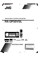
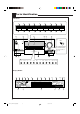
AUDIO/VIDEO CONTROL RECEIVER RX-DP20VSL DVD LEARN AUDIO TRANSMIT TV/DBS VCR 1 LEARN DVD MULTI PHONO VCR 1 VCR 2 TAPE/MD CDR TV/DBS DVD VIDEO FM/AM EXT 7.1CH ANALOG/DIGITAL CD EFFECT 1 INPUT 2 3 LIVENESS SOUND 4 5 6 7/P 8 9 TEST CC CONVERTER MASTER VOLUME THX STANDBY 10 0 RETURN FM MODE 100+ SURROUND DSP SURR/DSP +10 OFF DIMMER CC CONVERTER STANDBY/ON EX/ES/7.
Warnings, Cautions and Others IMPORTANT for the U.K. DO NOT cut off the mains plug from this equipment. If the plug fitted is not suitable for the power points in your home or the cable is too short to reach a power point, then obtain an appropriate safety approved extension lead or consult your dealer. BE SURE to replace the fuse only with an identical approved type, as originally fitted.
SAFETY INSTRUCTIONS “SOME DOS AND DON’TS ON THE SAFE USE OF EQUIPMENT” This equipment has been designed and manufactured to meet international safety standards but, like any electrical equipment, care must be taken if you are to obtain the best results and safety is to be assured. Do read the operating instructions before you attempt to use the equipment.
Introduction We would like to thank you for purchasing one of our JVC products. Before operating this unit, read this manual carefully and thoroughly to obtain the best possible performance from your unit, and retain this manual for future reference.
Table of Contents Parts Identification ...................................... 3 Getting Started ........................................... 7 Before Installation ...................................................................... 7 Checking the Supplied Accessories ........................................... 7 Connecting the FM and AM (MW/LW) Antennas ..................... 7 Connecting the Speakers ............................................................ 8 Connecting Audio/Video Components ..........
Parts Identification Front Panel 1 2 SPEAKERS 1 INPUT MODE THX SPEAKERS 2 INPUT ATT EX/ES/7.1 p 3 q o 4 w 5 6 7 8 9 SURROUND SURR/DSP OFF ADJUST MENU DOWN / TUNING ∞ UP / TUNING 5 SET / MEMORY DSP ANALOG DIRECT SETUP MENU LEFT / PRESET ∞ RIGHT / PRESET 5 EXIT / FM MODE e r t y u i a ; s d f g DOOR MASTER VOLUME STANDBY DOWN DIMMER CC CONVERTER STANDBY / ON DOOR UP RX-DP20V DOOR DOWN SPEAKERS 1 INPUT MODE SPEAKERS 2 INPUT ATT PHONES THX EX/ES/7.
Refer to the pages in parentheses for details. Front Panel Display Window 1 2 3 4 5 6 7 1 DUAL indicator (20) • Lights up when Dual Mono signals are detected. 2 ANALOG indicator (22) • Lights up when an analog input (source) is selected. 3 DGTL AUTO indicator (22) • Lights up when auto digital input (DIGITAL AUTO) is selected. 4 96/24 indicator (46) • Lights up when DTS 96/24 signals are detected. 5 Surround/THX/DSP mode indicators • Indicate the current Surround/THX/DSP mode setting.
Rear Panel 1 2 3 RIGHT MM DIGITAL IN 1 (DVD) 2 (CD) 3 (TV /DBS) 4 VIDEO AUDIO LEFT MC RIGHT TV SOUND DBS IN CD IN OUT (REC) TAPE MD IN (PLAY) IN (PLAY) IN (PLAY) PR OUT (REC) Y DVD IN MONITOR OUT 9 COMPU LINK-4 TEXT COMPU LINK (SYNCHRO) PB AM LOOP SUB WOOFER 2 IN FM 75 PR COAXIAL SURR BACK R L EXT 7.
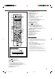
Remote Control 1 2 DVD LEARN TV/DBS 3 DVD DVD MULTI t PHONO CD VCR 1 VCR 2 TAPE/MD CDR TV/DBS VIDEO FM/AM EXT 7.1CH 1 2 ANALOG/DIGITAL 6 7 8 9 p q i o VCR 1 LEARN 4 5 AUDIO TRANSMIT y u i o ; EFFECT INPUT 3 LIVENESS SOUND 4 5 6 7/P 8 9 +10 ; TEST CC CONVERTER THX 10 0 RETURN FM MODE 100+ SURROUND DSP SURR / DSP a s d OFF w e EX / ES / 7.
Getting Started This section explains how to connect audio/video components and speakers to the receiver, and how to connect the power supply. Before Installation Connecting the FM and AM (MW/LW) Antennas General • Be sure your hands are dry. • Turn the power off on all components. • Read the manuals supplied with the components you are going to connect. Location • Install the receiver in a location that is level, well-ventilated and free from moisture.
AM (MW/LW) Antenna Connections 3 2 1 Connecting the Speakers For full enjoyment of the THX modes (see page 45), it is recommended to use THX-certified speakers. You can connect the following speakers: • Two pairs of front speakers to produce normal stereo sound. • One pair of surround speakers to produce a three-dimensional sound movement and environmental background-effect sounds. • One or one pair of surround back speakers to enjoy 6.1-channel or 7.1-channel sound reproduction.
Front speakers 1 Right / Left Center speaker FRONT 1 SPEAKERS CAUTION : SPEAKER IMPEDANCE IMPORTANT: After connecting the speakers, set the speaker setting information properly: • To obtain the best possible Surround/THX/DSP effect, see “Basic Settings” on pages 29 to 38. • To connect the speakers to the FRONT 2 SPEAKERS terminal, set the speaker terminal usage correctly. (See “w Setting the Speakers 2 Usage—SPEAKER 2” on page 37.
About the FRONT 2 SPEAKERS terminals The FRONT 2 SPEAKERS terminals can be used as follows: • To connect another pair of the front speakers. • To connect only one pairs of the speakers and to drive them using two amplifiers built in this receiver. If the speakers connected are of the bi-wiring connection type, you can connect the speakers as illustrated below. (You can use either front speaker terminals for high frequency or for low frequency terminals.
CD player Connecting Audio/Video Components RIGHT MM When connecting individual components, refer also to the manuals supplied with them. CD player Analog Connections Audio component connections Use the cables with RCA pin plugs (not supplied). • Connect the white plug to the audio left jack, and the red plug to the audio right jack.
IMPORTANT: External 7.1-channel output component A B Decoder (or DVD player) C D E AUDIO RIGHT R LEFT FRONT L CENTER SUB WOOFER L SURR R R SURR BACK L Å ı Ç Î ‰ This receiver is equipped with the following video jacks—composite video, S-video and component video jacks. You can use any of the three to connect a video component.
NOTICE: If you play back an NTSC tape on a VCR, the picture may be distorted and may not be displayed correctly.
Rear view TV and/or DBS tuner VIDEO AUDIO RIGHT R VIDEO LEFT TV SOUND DBS IN L COMPONENT S-VIDEO Y OUT (REC) PB VCR 1 1 IN (DVD) IN (PLAY) PR When connecting the TV to the AUDIO jacks (TV SOUND/DBS IN), DO NOT connect the TV’s video output to these video input jacks.
DVD player • When you connect the DVD player with stereo output jacks: VIDEO Rear view COMPONENT S-VIDEO Y Å To front left/right channel audio output (or to audiomixed output if necessary) ı To composite video output Ç To S-video output Î To component video output Y PB PB 1 IN (DVD) 2 IN PR PR 3 IN (REC) IN (PLAY) CDR FRONT DVD IN SUB WOOFER MONITOR OUT R FRONT Note: PR If the DVD player has component video output jacks, you can connect it to either the COMPONENT 1 IN (DVD), 2 IN, or 3 I
Notes: Digital Connections This receiver is equipped with six DIGITAL IN terminals—three digital coaxial terminals and three digital optical terminals—and one DIGITAL OUT (optical) terminal on the rear. • Another digital optical input terminal is located on the front panel (see page 12).
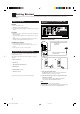
Connecting the Power Cord Putting Batteries in the Remote Control Before plugging the receiver into an AC outlet, make sure that all connections have been made. Before using the remote control, insert the two supplied batteries first. AC IN socket on Connect one end of the power cord to the the rear and the other end into an AC outlet. 1. On the back of the remote control, remove the battery cover. AC IN 2. Insert the batteries. • Make sure to match the polarity: (+) to (+) and (–) to (–).
Basic Operations This section explains only the operations commonly used when you play any sound source. • Before performing basic operations, it is recommended to finish the basic settings on pages 29 to 38. IMPORTANT: • When using the unit: Press DOOR DOWN to use the buttons inside the front door. To close the front door, press DOOR UP. 4. If no sound comes out of the front speakers, press SPEAKERS 1 and/or SPEAKERS 2 which you want to use.
Turning the Power On and Off (Standby) On the unit: To turn on the power, press (STANDBY/ON). The STANDBY lamp goes off, and the front door moves down (so that the source selecting buttons appear). Selecting the Source to Play Press one of the source selecting buttons. • The selected source name and Surround/THX/DSP mode also appear on the display. DVD DVD MULTI VCR 1 VCR 2 TV/DBS VIDEO CD PHONO TAPE/MD CDR FM/AM EXT 7.
Speaker and signal indicators on the display By checking the following indicators, you can easily confirm which speakers you are activating and which signals are coming into this receiver from the source. Speaker indicators L C Signal indicators R L C SUBWFR LS How to use the speaker and signal indicators To obtain the best performance of this receiver while using the Surround/THX/DSP modes, check the speaker and signal indicators on the display carefully and set the speakers correctly.
Notes: Adjusting the Volume MASTER VOLUME On the unit: To increase the volume, turn MASTER VOLUME clockwise. To decrease the volume, turn it Down Up counterclockwise. • When you turn MASTER VOLUME rapidly, the volume level also changes rapidly. • When you turn MASTER VOLUME slowly, the volume level also changes slowly. From the remote control: To increase the volume, press VOLUME +. To decrease the volume, press VOLUME –. VOLUME CAUTION: Always set the volume to the minimum before starting any source.
2. Press INPUT MODE (or ANALOG/DIGITAL INPUT) to change the input mode. When playing software encoded with the Dolby Digital or DTS Surround, the following symptoms may occur: • Sound does not come out at the beginning of playback. • Noise comes out while searching for or skipping chapters or tracks.
Muting the Sound Making Sounds Natural From the remote control ONLY: JVC’s CC (Compensative Compression) Converter eliminates jitter and ripples, achieving a drastic reduction in digital distortion by processing the digital music data in 24 bit–quantization and by expanding the sampling frequency to 128 kHz (for fs 32 kHz signals)/176.4 kHz (for fs 44.1 kHz signals)/192 kHz (for fs 48 kHz signals). By using the CC Converter, you can obtain a natural sound field from both digital and analog sources.
When changing the source name from “TV ” to “DBS”: TV/DBS 1. Press TV/DBS. Recording a Source For analog-to-analog recording 2. Press and hold TV/DBS until “ASSGN. DBS” appears on the display. ANALOG L SPEAKERS R 1 VOLUME SUBWFR dB To change the source name to “TAPE” or “TV,” repeat the same procedure above—press and hold TAPE/MD to select “TAPE,” or press and hold TV/DBS to select “TV” in step 2.
Receiving Radio Broadcasts You can browse through all the stations or use the preset function to go immediately to a particular station. IMPORTANT: Using Preset Tuning • When using the unit: Press DOOR DOWN to use the buttons inside the front door. Once a station is assigned to a channel number, the station can be quickly tuned in. You can preset up to 30 FM and 15 AM (MW/LW) stations. DOOR DOWN To store the preset stations Before you start, remember...
To tune in to a preset station Receiving FM Stations with RDS On the unit: FM/AM 1. Press FM/AM. RDS (Radio Data System) allows FM stations to send an additional signal along with their regular program signals. For example, the stations send their station names, as well as information about what type of program they broadcast, such as sports or music, etc. • When tuned to an FM station which provides the RDS service, the RDS indicator lights up on the display.
From the remote control ONLY: You can also show the RDS information on the TV screen. To use this function, you need to connect the TV to the MONITOR OUT jack on the rear panel (see page 14), and set the TV’s input mode to the proper position to which the receiver is connected. 1. Press PTY SEARCH while listening to an FM station. “PTY SELECT” flashes on the display. ANALOG L From the remote control ONLY: Press TEXT DISPLAY while listening to an FM station.
Switching to a Program of Your Choice Automatically When the current source is other than “FM” If a station starts broadcasting the program you have selected while listening to current source is other than “FM” When a station is or starts broadcasting the program you have selected, the receiver automatically switches to the station. The indicator of received PTY code starts flashing. CASE 3 Another convenient RDS service is called “Enhanced Other Networks.
Basic Settings Some of the following settings are required after connecting and positioning your speakers, while others will make operations easier. Setup Menu Configuration SETUP MENU (1) 1 SPEAKER SETTING (See page 32.) SETUP MENU (2) 8 DUAL MONO (See page 36.) 9 DIGITAL IN/OUT (See page 36.) 2 CHANNEL LEVEL (See page 32.) SETUP MENU (2) SETUP MENU (1) p VIDEO INPUT (See page 37.) 3 SPEAKER DISTANCE (See page 34.) q VIDEO POWER (See page 37.) w SPEAKER 2 (See page 37.) 4 SUBWOOFER (See page 34.
IMPORTANT: • When using the unit: Press DOOR DOWN to use the buttons inside the front door. Operation through On-Screen Display Menus To do the basic settings for this receiver, you can utilize the onscreen display menus in order to finish important settings easily while viewing these menus. DOOR DOWN Menu operation buttons • When no operation is done for about 1 minute, the on-screen menu (as well as the indications in the unit’s main display) will disappear. To close the front door, press DOOR UP.
Menu Operating Procedure Ex.When setting the speaker distance On the TV screen Operations On the main unit’s display 1. Press SETUP MENU. SPEAKERS 1 VOLUME dB The submenu names previously selected appears. SETUP MENU (1) appears. 2. Press fi or % (DOWN or UP) repeatedly to select the desired submenu. Press the button until “SP (speaker) DISTANCE” appears. Move to “SPEAKER DISTANCE.” • In this example, select “SPEAKER DISTANCE” submenu. SPEAKERS 1 VOLUME dB 3. Press SET.
1 Setting the Speakers—SPEAKER SETTING To obtain the best possible surround sound of the Surround/ THX/DSP modes in, you have to register the information about the speaker arrangement after all connections are completed. 7 SUBWOOFER Register whether you have connected a subwoofer. YES : Select when a subwoofer is connected. NO : Select when no subwoofer is used.
7 TEST TONE You can emit the test tone to adjust the speaker output level. CAUTION: The test tone is automatically fixed to 0 dB, but this level will be louder than you would expect. Select one of the following. • The test tone will be heard for about three seconds after you select “AUTO” or “MANUAL.
3 Setting the Speaker Distance —SPEAKER DISTANCE 4 Setting the Bass Sounds—SUBWOOFER The distance from your listening point to the speakers is another important element to obtain the best possible surround sound of the Surround/THX/DSP modes. You need to set the distance from your listening point to the speakers.
7 BASS PEAK LIMIT 5 Setting the THX Audio—THX AUDIO SETUP When this setting is “ON,” Bass Peak Limit functions so that sounds exceeding the preset peak level (see below) will be cut off. These settings are required to obtain the optimum effect from the THX modes. When this setting is “ON,” you can set the bass peak level using the bass test tone (see below) to eliminate bass sound distortion. Select one of the following: ON : Normally select this. Note: OFF : Select when not using Bass Peak Limit.
6 Setting the Surround Channel Output Speakers—SURR CH OUT On this submenu screen, you can preset which surround speakers to use for 5.1 channel reproduction. Note: This submenu is not available in the following cases: – When “SURR BACK OUT” is set to “1SPK” on the SPEAKER SETTING submenu, – “SURR BACK SP” is set to “NONE” on the SPEAKER SETTING submenu, or – “SPEAKER 2” is set to “BI-AMP OUT” on the SPEAKER 2 submenu.
7 DIGITAL OUT Select the output digital signal format through the DIGITAL OUT (optical) terminal on the rear. • Each time you press the button, the output signal format changes as follows: q Turning On and Off the Video Output —VIDEO POWER On this submenu screen, you can turn on or off the power supply to the video output circuit built in this unit. THROUGH : Select when connecting a digital signal processor or decoder.
e Superimposing the Menus—SUPERIMPOSE You can select whether or not to superimpose the menus on the playback pictures on the TV screen. t Memorizing the Volume Level for Each Source—ONE TOUCH OPE This unit memorizes many settings separately for each source (see page 24). In addition, you can store the volume level for each source together with the other memorized settings.
Sound Adjustments Sound adjustment operations are easily done on the Adjustment menu. Some of the adjustments can also be done directly using the buttons on the remote control. Adjustment Menu Configuration ADJUST MENU 1 PARAMETRIC EQ (See page 42.) 2 MIDNIGHT MODE (See page 43.) 3 EFFECT ADJUST (See page 43.) (When DSP is activated) (When Pro Logic II Music is activated) (When Neo:6 Music is activated) (When one of the other modes is activated, or when the source is “DVD MULTI” or “EXT 7.
IMPORTANT: • When using the unit: Press DOOR DOWN to use the buttons inside the front door. Operation through On-Screen Display Menus To make sound adjustments for this receiver, you can utilize the onscreen display menus in order to finish important adjustments easily while viewing these menus. DOOR DOWN Menu operation buttons • When no operation is done for about 1 minute, the on-screen menu (as well as the indications in the unit’s main display) will disappear. To close the front door, press DOOR UP.
Menu Operating Procedure Ex.When adjusting the DSP effects On the TV screen Operations On the main unit’s display 1. Press ADJUST MENU. SPEAKERS 1 VOLUME • Make sure one of the DSP modes except “ALL CH STEREO” is selected. dB The submenu names previously selected appears. ADJUST MENU appears. 2. Press fi or % (DOWN or UP) repeatedly to select the desired submenu. Move to “EFFECT ADJUST.” Press the button until “EFFECT ADJ” appears. • In this example, select “EFFECT ADJUST” submenu.
1 Adjusting the Parametric Equalizer for Each Channel—PEQ FRONT/CENTER/ SURROUND/SURR BACK 7 Submenu items On this submenu, you can adjust the following items for each channel: You can adjust equalization patterns to your preference. First, on the ADJUST MENU screen, select the signal channel (speaker) you want to adjust, then move to its submenu. Notes: • If “NO” or “NONE” is selected for a speaker on the SPEAKER SETTING submenu (see page 32), you cannot select the corresponding channel.
2 Setting the Midnight Mode—MIDNIGHT MODE Using the Midnight mode, you can enjoy a powerful sound at night even at a low volume level. 7 MIDNIGHT MODE Select one of the following: 1 : Select when you want to reduce the dynamic range a little. The MIDNIGHT MODE indicator lights up on the display. 2 : Select when you want to apply the compress effect fully (useful late at night). The MIDNIGHT MODE indicator lights up on the display.
• When Dolby Pro Logic II Music is activated: • When one of the other Surround modes is activated, or “DVD MULTI” or “EXT 7.1CH” is selected (without DSP mode): Select and adjust the following items: CENTER EQ: In movie theaters, the screen works as the highfrequency cut filter of the center channel since the center speakers are located behind the screen and the center channel sounds have to pass through the screen.
Using the Surround and THX Modes This unit activates a variety of Surround and THX modes automatically. The stored basic settings and adjustments performed on the Setup and Adjustment Menus (see pages 29 to 44) are applied. Reproducing Theater Ambience In a movie theater, many speakers are located on the walls to reproduce impressive multi-surround sounds, reaching you from all directions. With these many speakers, sound localization and sound movement can be expressed.
Dolby Digital EX DTS Extended Surround (DTS-ES) Dolby Digital EX (DOLBY D EX) is a new digital surround encoding format that adds the third surround channels, called “surround back.” Compared to the conventional Dolby Digital 5.1CH, the newly added surround back channel can reproduce more detailed movements behind you while viewing the video software. In addition, surround sound localization will become more stable. DTS-ES is another new multi-channel digital encoding format.
Surround and THX Modes Applicable to the Various Software Available Surround modes and THX modes vary depending on the speaker settings and the incoming signals. The tables from this page to the next page show the relation of the Surround/THX modes and the incoming signals (with surround back speakers and 7.1-channel reproduction mode settings). • If only front speakers are activated, you cannot use the THX modes and the 7.1-channel reproduction mode (ES/EX/7.1).
Incoming Signal Type (multi-channel) Surround Back Ch (NONE/1SPK/2SPK) 2SPK/1SPK DTS-ES Discrete 6.1ch ES/EX/7.
Activating the Surround and THX Modes Perform the basic settings and adjustments using the Setup and Adjustment Menus first (see pages 29 to 44). Activating the Surround mode and the THX mode for a source automatically recalls the memorized settings and adjustments. IMPORTANT: • When using the unit: Press DOOR DOWN to use the buttons inside the front door. Activating the 7.1-channel reproduction For multi-channel digital software, you can activate the 7.1-channel reproduction mode. • Once you have set 7.
Activating the Surround Modes For the Surround modes, Parametric Equalizer adjustments done on the Adjustment menu also take effect for the activated speaker channels. • Available Surround modes vary depending on the received signal and the current speaker settings. For details, see “Surround and THX Modes Applicable to the Various Software” on pages 47 and 48. 1. Select and play any source other than “DVD MULTI” and “EXT 7.1CH.” • Surround modes are not applicable to “DVD MULTI” and “EXT 7.1CH.” 2.
Activating the THX Modes When one of the THX modes is activated, Parametric Equalizer, and CC Converter are temporarily canceled. • Available THX modes vary depending on the received signal and the current speaker settings. For details, see “Surround and THX Modes Applicable to the Various Software” on pages 47 and 48. 1. Select and play any source other than “DVD MULTI” and “EXT 7.1CH.” • To use the THX modes for “DVD MULTI” and “EXT 7.1CH,” see page 54.
Using the DSP Modes This unit provides a variety of DSP (Digital Signal Processor) modes. The stored basic settings and adjustments performed on the Setup and Adjustment Menus (see pages 29 to 44) are applied. Reproducing the Sound Field The sound heard in a concert hall, club, etc. consists of direct sound and indirect sound—early reflections and reflections from behind. Direct sounds reach the listener directly without any reflection.
All Channel Stereo mode This mode can reproduce a larger stereo sound field using all the connected (and activated) speakers. This mode cannot be used without activating the surround speakers. • If headphones are connected or if the front speakers are deactivated, “ALL CH STEREO” cannot be selected. • The settings on the EFFECT ADJUST submenu are not valid for “ALL CH STEREO.” 1. Select and play any sound source. 2. Press DSP repeatedly until the DSP mode you want appears on the display.
Using the Analog Multi-channel Playback Mode This receiver provides the DVD MULTI and EXT 7.1CH playback modes for reproducing the analog discrete output mode of the DVD player or another component such as a digital decoder. Before using these playback modes, refer also to the manual supplied for those components. 3. Apply the THX mode or the DSP mode if necessary.
COMPU LINK Remote Control System The COMPU LINK remote control system allows you to operate JVC audio components through this receiver. To use this remote control system, you need to connect JVC audio components through the COMPU LINK (SYNCHRO) jacks (see below) in addition to the connections using cables with RCA pin plugs (see page 11). • Make sure that the AC power cords of these components are unplugged before connection. Plug the AC power cords only after all connections are complete.
TEXT COMPU LINK Remote Control System The TEXT COMPU LINK remote control system has been developed to deal with the disc information recorded in the CD Text* and MDs. Using this information in the discs, you can operate the CD player or MD recorder with the TEXT COMPU LINK remote control system through the receiver. CONNECTIONS FUNCTIONS To use this remote control system, you need to connect the CD player and/or MD recorder you want to operate, following the procedures below. 1.
OPERATIONS To use this remote control system, you need to connect the TV to the MONITOR OUT jack (see page 14), and set the TV’s input mode to the proper position to which the receiver is connected. Make sure you have connected the CD player or MD recorder equipped with the TEXT COMPU LINK remote control system. If not, you cannot use the following functions.
Searching for a Disc (Only for the CD player) Search for a disc by its performer: 1. Press TEXT DISPLAY while “CD” is selected as the source. The Disc Information screen appears on the TV. 2. Press % / fi to move SET. to “SEARCH,” then press 1. Press TEXT DISPLAY while “CD” is selected as the source. The Disc Information screen appears on the TV. 2. Press % / fi to move SET. to “SEARCH,” then press The DISC SEARCH screen appears. The DISC SEARCH screen appears. 3.
Search for a disc by its genre: 1. Press TEXT DISPLAY while “CD” is selected as the source. The Disc Information screen appears on the TV. 2. Press % / fi to move press SET. to “SEARCH,” then The DISC SEARCH screen appears. 3. Press % / fi to move to “GENRE,” then press SET. The GENRE SEARCH screen appears. 4. Press % / fi to move to the genre you want to search for, then press SET. To show the unseen genres, press % / fi until they appear.
For the MD recorder: 4. Repeat step 3 until you finish entering a performer name (up to 32 characters). To insert a space, press % / fi / @ / # to move , then press SET. to To correct an incorrect character: 1) Press % / fi / @ / # to move to + or =, then press SET until the incorrect character is selected. 2) Press % / fi / @ / # to move to , then press SET to erase the character. in front of the correct 3) Press % / fi / @ / # to move character, then press SET to enter the correct character. 1.
Operating JVC’s Audio/Video Components You can operate JVC’s audio and video components with this receiver’s remote control, since control signals for JVC components are preset in the remote control.
CD player After pressing CD, you can perform the following operations on the CD player: PLAY 4 ¢ STOP PAUSE 1 – 10, +10 : Starts playing. : Returns to the beginning of the current (or previous) track. : Skips to the beginning of the next track. : Stops playing. : Pauses playing. To release, press PLAY. : Selects a track number directly. For track number 5, press 5. For track number 15, press +10, then 5. For track number 20, press +10, then 10. For track number 30, press +10, +10, then 10.
VCR (VCR connected to the VCR 1 jacks) Operating Video Components You can always perform the following operations: IMPORTANT: VCR 1 To operate JVC’s video components using this remote control: • Some JVC VCRs can accept two types of the control signals— remote codes “A” and “B.” Before using this remote control, make sure that the remote control code of the VCR connected to the VCR 1 jacks is set to code “A.
Operating Other Manufacturers’ Equipment You can use this remote control supplied for operating other manufacturers’ components, either by changing the preset signal codes or by using the learning function (see page 68). IMPORTANT: Changing the Preset Signal Codes When using the remote control: – Set the TV operation mode selector to “TV” or TV “CATV/DBS” correctly. CATV/ To operate TV, set it to “TV.” DBS To operate the CATV converter or the DBS tuner, set it to “CATV/DBS.
To change the transmittable signals for operating another manufacturer’s VCR To change the transmittable signals for operating another manufacturer’s CATV converter and DBS tuner 1. Set the TV operation mode selector to “CATV/DBS.” 1. Press and hold VCR 1 . VCR 1 TV CATV/ DBS 2. Press VCR 1. 2. Press and hold TV/DBS . VCR1 TV/DBS Remote’s display 3. Press TV/DBS. TV/DBS 3. Enter a manufacturer’s code using buttons 1–9, and 0. See page 67 to find the code. Remote’s display 4.
To change the transmittable signals for operating another manufacturer’s DVD player 1. Press and hold DVD 3. Enter a manufacturer’s code using buttons 1–9, and 0. See page 67 to find the code. DVD . 2. Press DVD. 3 LIVENESS 4 5 6 7/P 8 9 10 0 +10 RETURN FM MODE 100+ 3. Enter a manufacturer’s code using buttons 1–9, and 0. See page 67 to find the code. 4. Release DVD .
Manufactures’ codes for DBS tuner Manufacturer JVC Amstrad Blaupunkt Echostar General Instrument Goldstar Grundig Hirshmann ITT/Nokia Kathrein NEC Orbitech Philips RCA Samsung Schwaiger Siemens Sony Technisat Codes 56, 57*, 67 43, 44, 45, 46, 47, 48, 49 30 50, 51, 67 68 31 32, 33 48, 52, 53, 54, 55 34 52, 58, 59, 60, 61, 62, 63 35, 36 48 37, 38 65 39, 40 61, 64 41, 42 66 48 *This figure is set to the remote control as the initial JVC code.
Storing the Remote Signals Manually You can store the signals into the learning buttons by sending the signals you want to store from another remote control. This function is called “Learning Function.” To store the signals Before storing another manufacturer’s signals, make sure that the manufacturer’s remote control unit (hereafter called “target remote control”) actually works. 1. Set the LEARN/TRANSMIT selector to “LEARN.
4. Press one of the learning buttons, to which you want to assign a signal from the target remote control. The LEARN indicator starts flashing.
To use the stored signals To erase the stored signals When you want to use the stored signals, follow the procedure below. After erasing the stored signals, preset signals are resumed and you can operate JVC’s components again. IMPORTANT: To operate the other component(s) using this remote control— • Aim directly at the remote sensor(s) on the target component(s). – This remote control can send signals at a distance of 7 m. 1. Set the LEARN/TRANSMIT selector to “LEARN.” LEARN TRANSMIT 2.
Troubleshooting Use this chart to help you solve daily operational problems. If there is any problem you cannot solve, contact your JVC service center. General Sounds Surround/THX PROBLEM POSSIBLE CAUSE SOLUTION The “SPEAKER 2” setting is set to “BI-AMP OUT” on the SPEAKER 2 submenu. To use the 7.1-channel reproduction mode, set the “SPEAKER 2” setting to “SPEAKER 2,” then activate the surround back speaker(s). The “SURR BACK SP” setting is set to “NONE.
Additional Information Description of the PTY codes NEWS News. CHILDREN Programs targeted at a young audience. AFFAIRS Topical program expanding or enlarging upon the news—debate, or analysis. SOCIAL Programs about sociology, history, geography, psychology, and society. INFO Programs the purpose of which is to impart advice in the widest sense. RELIGION Religious programs. PHONE IN SPORT Programs concerned with any aspect of sports.
Specifications Amplifier Output Power At Stereo operation (Analog Direct On): Front channels: 120 W per channel, min. RMS, driven into 8 Ω, 20 Hz to 20 kHz with no more than 0.02% total harmonic distortion. 120 W per channel, min. RMS, driven into 4 Ω, 20 Hz to 20 kHz with no more than 0.07% total harmonic distortion. 130 W per channel, min. RMS, driven into 8 Ω at 1 kHz, with no more than 0.8% total harmonic distortion.
Video Video Input Sensitivity/Impedance: Composite video: S-video: Component: Video Output Level: Composite video: S-video: Component: Synchronization: Signal-to-Noise Ratio: DVD IN, VCR 1 IN, VCR 2 IN, TV SOUND/DBS IN, VIDEO: 1 V(p-p)/75 Ω DVD IN, VCR 1 IN, VCR 2 IN, TV SOUND/DBS IN, VIDEO: (Y: luminance): 1 V(p-p)/75 Ω (C: chrominance, burst): 0.286 V(p-p)/75 Ω 1 IN (DVD), 2 IN, 3 IN: (Y: luminance): 1 V(p-p)/75 Ω (PB, PR): 0.
RX-DP20VSL AUDIO/VIDEO CONTROL RECEIVER VICTOR COMPANY OF JAPAN, LIMITED EN © 2003 VICTOR COMPANY OF JAPAN, LIMITED RX-DP20VSL[B]COVER_f.pdf 2 0503NHMMDWJEM 03.5.