English Français AUDIO/VIDEO CONTROL RECEIVER RECEPTEUR DE COMMANDE AUDIO/VIDEO RX-DP15B INSTRUCTIONS MANUEL D’INSTRUCTIONS LVT1216-002A [C] Cover_RX-DP15B[C]f.pm6 3 04.4.
Warnings, Cautions and Others Mises en garde, précautions et indications diverses CAUTION RISK OF ELECTRIC SHOCK DO NOT OPEN CAUTION: TO REDUCE THE RISK OF ELECTRIC SHOCK. DO NOT REMOVE COVER (OR BACK) NO USER SERVICEABLE PARTS INSIDE. REFER SERVICING TO QUALIFIED SERVICE PERSONNEL.
For U.S.A. This equipment has been tested and found to comply with the limits for a Class B digital device, pursuant to part 15 of the FCC Rules. These limits are designed to provide reasonable protection against harmful interference in a residential installation. This equipment generates, uses and can radiate radio frequency energy and, if not installed and used in accordance with the instructions, may cause harmful interference to radio communications.
English Introduction We would like to thank you for purchasing one of our JVC products. Before operating this unit, read this manual carefully and thoroughly to obtain the best possible performance from your unit, and retain this manual for future reference. Features Precautions THX Ultra2 certified THX Ultra2 standard ensures the highest sound and picture quality and the most reliable performance by using seven-channel amplification to reproduce multi-channel software.
Parts Identification ...................................... 3 Getting Started ........................................... 7 Before Installation ...................................................................... 7 Checking the Supplied Accessories ........................................... 7 Connecting the FM and AM Antennas ....................................... 7 Connecting the Speakers ............................................................ 8 Connecting Audio/Video Components ..................
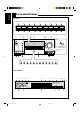
English Parts Identification Front Panel 1 2 SPEAKERS 1 INPUT MODE / INPUT ATT THX SPEAKERS 2 / ZONE 2 ZONE 2 CONTROL EX/ES/7.
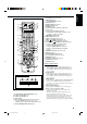
English Refer to the pages in parentheses for details. Front Panel Display Window 1 SPEAKERS 1 button (20, 25) 2 INPUT MODE button (25) INPUT ATT button (26) 3 THX button (57, 60) 4 SURROUND button (56, 57) 5 SURR/DSP OFF button (56, 57, 59, 60) 6 ADJUST MENU button (46) 7 DOWN button (36, 46) TUNING ∞ button (33) 8 UP button (36, 46) TUNING 5 button (33) 9 SET button (36, 46) MEMORY button (34) p SPEAKERS 2 button (20, 25) ZONE 2 button (32) q ZONE 2 CONTROL button (21, 29) w EX/ES/7.
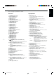
English Rear Panel 1 2 3 4 5 VIDEO AUDIO RIGHT DIGITAL IN 1 (DVD) 2 (CD) 3 (TV /DBS) RIGHT LEFT PHONO IN CD IN OUT (REC) TAPE MD IN (PLAY) 6 (VCR 1) IN (PLAY) FRONT Y PB PB VCR 1 1 IN (DVD) IN (PLAY) PR OUT (REC) Y CDR FRONT DVD IN SUB WOOFER MONITOR OUT 2 IN DVD IN SUB WOOFER 10mA MAX BAND2 COAXIAL R L FRONT 1 SPEAKERS FRONT 2 / ZONE 2 SPEAKERS CENTER SPEAKER CAUTION : SPEAKER IMPEDANCE 8 – 16 SURROUND SURROUND BACK SPEAKERS SPEAKERS Y PB CAUTION : SPEAKER
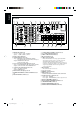
LEARN TRANSMIT 1 STANDBY 2 3 ZONE 1 ZONE 1 ZONE 2 ZONE 2 ON/OFF ON/OFF ZONE 1 4 TV/CATV/DBS VCR 1 STANDBY/ON STANDBY/ON ZONE 2 i o ; a ON 7 8 9 p q w e r LEARN t 5 DVD DVD MULTI PHONO CD VCR 1 VCR 2 TAPE/MD CDR TV/DBS VIDEO FM/AM EXT 7.1CH 1 2 ANALOG/DIGITAL 6 7 8 9 p q EFFECT INPUT 3 LIVENESS SOUND 4 5 6 7/P 8 9 s TEST CC CONVERTER THX 10 0 RETURN FM MODE 100+ SURROUND DSP SURR / DSP +10 d f g OFF w e EX / ES / 7.
English Getting Started This section explains how to connect audio/video components and speakers to the receiver, and how to connect the power supply. Before Installation Connecting the FM and AM Antennas General • Be sure your hands are dry. • Turn the power off on all components. • Read the manuals supplied with the components you are going to connect. Location • Install the receiver in a location that is level, well-ventilated and free from moisture and dust.
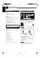
2 1 English AM Antenna Connections Connecting the Speakers 3 For full enjoyment of the THX modes (see page 51), it is recommended to use THX-certified speakers. You can connect the following speakers: • Two pairs of front speakers to produce normal stereo sound. • One pair of surround speakers to produce a three-dimensional sound movement and environmental background-effect sounds. • One or one pair of surround back speakers to enjoy 6.1-channel or 7.1-channel sound reproduction.
English Front speakers 1 Right / Left Center speaker FRONT 1 SPEAKERS CAUTION : SPEAKER IMPEDANCE FRONT 1 AND 2 / ZONE 2: 8 – 16 FRONT 1 OR 2: 4 – 16 IMPORTANT: After connecting the speakers, set the speaker setting information properly: • To obtain the best possible Surround/THX/DSP effect in Zone 1, see “Basic Settings” on pages 35 to 44. • To connect the speakers to the FRONT 2/ZONE 2 SPEAKERS terminals, set the speaker usage correctly.
Left front speaker Rear view HIGH Enhance your audio system You can use this receiver as the pre-amplifier (control amplifier) when you connect power amplifiers to the PREOUT jacks on the rear panel, using cables with RCA pin plugs (not supplied). • Connect the white plug to the audio left jack, and the red plug to the audio right jack.
English CD player Connecting Audio/Video Components AUDIO When connecting individual components, refer also to the manuals supplied with them. RIGHT CD player Analog Connections Audio component connections Use the cables with RCA pin plugs (not supplied). • Connect the white plug to the audio left jack, and the red plug to the audio right jack.
A B Decoder (or DVD player) C D E AUDIO RIGHT R LEFT FRONT L CENTER SUB WOOFER L SURR R R SURR BACK L Å ı Ç Î ‰ This receiver is equipped with the following video jacks—composite video, S-video and component video jacks. You can use any of the three to connect a video component. However, observe the following points when make connections: • Composite video signals and S-video signals can be converted into each other, and can be also converted into component signals.
English Rear view VCR(s) A D-VHS/S-VHS/VHS VCR B C VIDEO AUDIO RIGHT VIDEO LEFT E F G R OUT (REC) PB L VCR 1 1 IN (DVD) R IN (PLAY) PR OUT (REC) Y Y PB 2 IN PR L Green VCR 2 PB Blue 3 IN DVD IN FRONT Red VIDEO VIDEO LEFT L COMPONENT S-VIDEO TV SOUND DBS IN R • If the VCR has component video output jacks, you can connect it to either the COMPONENT 1 IN (DVD), 2 IN, or 3 IN jacks.
English Rear view TV and/or DBS tuner VIDEO AUDIO RIGHT R VIDEO LEFT TV SOUND DBS IN L COMPONENT S-VIDEO Y OUT (REC) PB VCR 1 1 IN (DVD) IN (PLAY) PR When connecting the TV to the AUDIO jacks (TV SOUND/DBS IN), DO NOT connect the TV’s video output to these video input jacks.
English DVD player • When you connect the DVD player with stereo output jacks: VIDEO Green Y Y PB PB Blue Å To front left/right channel audio output (or to audiomixed output if necessary) ı To composite video output Ç To S-video output Î To component video output 1 IN (DVD) 2 IN Red PR PR 3 IN (REC) IN (PLAY) R FRONT CDR FRONT DVD IN PR SUB WOOFER MONITOR OUT Y Notes: CENTER L MONITOR OUT SURR SUB WOOFER CENTER R PR R L B C MONITOR OUT ZONE 2 PREOUT DVD player L PREOU
This receiver is equipped with six DIGITAL IN terminals—three digital coaxial terminals and three digital optical terminals—and one DIGITAL OUT (optical) terminal on the rear. • Another digital optical input terminal is located on the front panel (see page 12).
English Using the RF Rod Antenna and IR Signal Transmitter The combination of the RF rod antenna and the IR signal transmitter allows you to use the multi-room function more conveniently. The remote control supplied for this receiver can transmit both RF signal and IR signal at the same time.
Putting Batteries in the Remote Control Before using the remote control, insert the two supplied batteries first. Target component(s) 2 1 L COMPU LINK-4 es AV s COMPU (SYNCHRO) LINK- an th TEXT COMPU LINK IR OUT 3 LR6(AM3) /L40(15A) CTRL OUT +12V 3 m (1 0 e fe t) IR IN 10mA MAX At an angle of approx. 60° 1. On the back of the remote control, remove the battery cover. Signal-emitting angle of the transmitter Horizontally: 60˚ Vertically: 60˚ 2. Insert the batteries.
English Multi-Room Operations Before operating this receiver any further, be familiar with this multi-room function. This function enables you to listen to different sources in two different places (we call these two places “Zone 1 (main room)” and “Zone 2 (sub-room)”) by using this receiver. This section explains only the required speaker connections, the concept, and basic operations of the multi-room function. For more detailed operations, see the respective pages in this manual.
1. Set ZONE 1/ZONE 2 (LEARN/ TRANSMIT) selector to “ZONE 1.” On the unit: 1. Press (STANDBY/ON). The STANDBY lamp goes off, and the ZONE 1 ON/OFF lamp lights up. The front door moves down so that the source selecting buttons appear, and the buttons and controls on the unit work for the Zone 1 operations. • For more details, see “Turning the Power On and Off (Standby)” on page 22. STANDBY Now the buttons and controls on the remote control work for the Zone 1 operations. ZONE 1 ZONE 2 2.
English 6. Turn MASTER VOLUME to adjust the volume level of the sound through the Zone 2 front speakers. Basic Operating Procedure for Zone 2 The sources and functions available for the Zone 2 operations are limited. For more details on the Zone 2 operations, see “Zone 2 (Subroom) Operations” on pages 29 to 32. 1. Press Down Note: On the unit: (STANDBY/ON). The STANDBY lamp goes off, and the ZONE 1 ON/OFF lamp lights up.
English Zone 1 (Main Room) Operations This section explains only the operations commonly used when you play any sound source in Zone 1 (main room). See pages 29 to 32 for the Zone 2 (sub-room) operations. • Before performing Zone 1 operations, it is recommended to finish the basic settings on pages 35 to 44. IMPORTANT: Check the following before or while using the buttons and controls. For Zone 1 operations: The ZONE 1 ON/OFF lamp on the unit is lit.
English Canceling the Zone 1 Operations To stop Zone 1 operations and sounds from the Zone 1 speakers, press ZONE 1 ON/OFF so that the ZONE 1 ON/OFF lamp goes off. ZONE 1 ON/OFF ZONE 1 ON/OFF From the remote control On the unit The currently selected front speakers indicator(s) also go(es) off from the display (no sound will be heard in Zone 1). To use this receiver for Zone 1 operations again, press ZONE 1 ON/OFF again (the ZONE 1 ON/OFF lamp lights up).
Selecting different sources for picture and sound While watching pictures from a video source (DVD player, VCR, or DBS tuner), you can listen to sound of an audio source. • Once you have selected a video source, pictures of the selected source are sent to the TV until you select another video source. Press one of the audio source selecting buttons— PHONO, CD, TAPE/MD, CDR, FM/AM, EXT 7.1CH—while viewing the picture from a video component such as the VCR or DVD player, etc.
English Activating the Zone 1 Front Speakers When shipped from the factory, both pairs of the front speakers have been set to be used in Zone 1. • To connect the speakers to the FRONT 2/ZONE 2 SPEAKERS terminals, set the speaker usage correctly. (See “w Setting the Zone 2/Speakers 2 Usage—ZONE 2/ SPEAKER 2” on page 43.) On the unit ONLY: When you have connected two pairs of front speakers and placed them in Zone 1, you can select which to use.
ANALOG : Select this for the analog input mode. The ANALOG indicator lights up. Attenuating the Input Signal When the input level of the playing source is too high, the sounds will be distorted. If this happens, you need to attenuate the input signal level to prevent sound distortion. • You have to make this setting for analog each source. On the unit ONLY: Press and hold INPUT ATT (inside the front door) so that the INPUT ATT indicator lights up on the display.
English Changing the Display Brightness Making Sounds Natural You can dim the display. Press DIMMER. • Each time you press the button, the brightness level of the display changes as follows: DIMMER DIMMER On the unit Press CC CONVERTER so that the CC CONVERTER lamp lights up.
Notes: • Once you change the source name, it is applied both for the Zone 1 and Zone 2 sources. • Without changing the source name, you can still use the connected components. However, there may be some inconvenience: – “TAPE” or “TV” will appear on the display when you select the MD recorder or DBS tuner. – You cannot use the digital input (see page 25) for the MD recorder. – You cannot use the COMPU LINK or TEXT COMPU LINK remote control system (see pages 61 and 63) to operate the MD recorder.
English Zone 2 (Sub-room) Operations This section explains only the operations used when you play a sound source in Zone 2. See pages 22 to 28 for the Zone 1 operations. • Before performing the Zone 2 operations, it is recommended to finish the basic settings on pages 35 to 44. IMPORTANT: Check the following before or while using the buttons and controls.
English To turn off the power (into standby mode), STANDBY (STANDBY/ON) again. press The STANDBY lamp lights up, and the front STANDBY/ON door automatically closes. (The ZONE 1 ON/ OFF and/or ZONE 2 ON/OFF lamp goes off.) • A small amount of power is consumed in standby mode. To turn the power off completely, unplug the AC power cord. Canceling the Zone 2 Operations On the unit: To stop Zone 2 operations and sounds through the Zone 2 speakers, press ZONE 2 ON/OFF so that the ZONE 2 ON/OFF lamp goes off.
English Selecting different sources for picture and sound Selecting the Zone 2 Source to Play Press one of the source selecting buttons. DVD DVD MULTI VCR 1 VCR 2 TV/DBS VIDEO CD PHONO TAPE/MD CDR FM/AM EXT 7.1CH While watching pictures from a video source (DVD player, VCR, or DBS tuner), you can listen to sound of an audio source. • Once you have selected a video source, pictures of the selected source are sent to the TV until you select another video source.
This section is NOT applicable to those who connect the Zone 2 front speakers through the ZONE 2 PREOUT jacks through another amplifier (see page 19). From the remote control ONLY: On the unit ONLY: MUTING Press MUTING to mute the sound through the Zone 2 front speakers. Before you start, remember... • When shipped from the factory, both pairs of the front speakers have been set to be used in Zone 1.
English Receiving Radio Broadcasts You can browse through all the stations or use the preset function to go immediately to a particular station. Indicates the functions YOU CAN ALSO USE when the receiver is ready for Zone 2 operations. IMPORTANT: Check the following before or while using the buttons and controls. Tuning in to Stations Manually 1. Press FM/AM. The last received station of the last selected band is tuned in. • Each time you press the button, the band alternates between FM and AM.
Once a station is assigned to a channel number, the station can be quickly tuned in. You can preset up to 30 FM and 15 AM stations. English 2. Press PRESET 5 / ∞ (inside the front door) until you find the channel you want. Using Preset Tuning RIGHT / PRESET LEFT / PRESET From the remote control: To store the preset stations FM/AM 1. Press FM/AM. Before you start, remember... • There is a time limit in doing the following steps. If the setting is canceled before you finish, start from step 1 again.
English Basic Settings Some of the following settings are required after connecting and positioning your speakers, while others will make operations easier. Basic setting operations are only possible while the receiver is ready for Zone 1 operations. Setup Menu Configuration SETUP MENU (2) SETUP MENU (1) SETUP MENU 1 SPEAKER SETTING CHANNEL LEVEL SPEAKER DISTANCE SUBWOOFER THX AUDIO SETUP SURR CH OUT AUDIO DELAY NEXT PAGE :ENTER :EXIT 1 SPEAKER SETTING (See page 38.
Check the following before or while using the buttons and controls. English IMPORTANT: Operation through On-Screen Display Menus For Zone 1 operations: The ZONE 1 ON/OFF lamp on the unit is lit. • When using the unit: – “ZONE 2” is not shown in the main display. – Press DOOR DOWN to use the buttons inside the front door. To close the front door, press DOOR UP.
English Menu Operating Procedure Ex.When setting the speaker distance On the TV screen Operations 1. Press SETUP MENU. On the main unit’s display SETUP MENU 1 SPEAKERS 1 VOLUME SPEAKER SETTING CHANNEL LEVEL SPEAKER DISTANCE SUBWOOFER THX AUDIO SETUP SURR CH OUT AUDIO DELAY NEXT PAGE :ENTER :EXIT dB The submenu names previously selected appears. SETUP MENU (1) appears. 2. Press fi or % (DOWN or UP) repeatedly to select the desired submenu. Move to “SPEAKER DISTANCE.
SPEAKER SETTING SUBWOOFER : FRONT SP : CENTER SP : SURROUND SP : SURR BACK SP : SURR BACK OUT: CROSSOVER : NO LARGE SMALL SMALL SMALL 2SPK 80Hz :OPERATE :BACK To obtain the best possible surround sound of the Surround/ THX/DSP modes in Zone 1, you have to register the information about the speaker arrangement after all connections are completed. 7 CROSSOVER You can select the crossover frequency for the small speakers used.
English 7 TEST TONE You can emit the test tone to adjust the speaker output level. CAUTION: The test tone is automatically fixed to 0 dB, but this level will be louder than you would expect. Select one of the following. • The test tone will be heard for about three seconds after you select “AUTO” or “MANUAL.
4 Setting the Bass Sounds—SUBWOOFER SUBWOOFER The distance from your listening SPEAKER DISTANCE point to the speakers is another UNIT : meter SUBWOOFER : 3.00m important element to obtain the FRONT L SP : 3.00m FRONT R SP : 3.00m best possible surround sound of CENTER SP : 3.00m the Surround/THX/DSP modes. SURR L SP : 3.00m SURR R SP : 3.00m You need to set the distance from SBACK L SP : 3.00m SBACK R SP : 3.00m your listening point to the :OPERATE :BACK speakers.
English 7 BASS PEAK LIMIT 5 Setting the THX Audio—THX AUDIO SETUP When this setting is “ON,” Bass Peak Limit functions so that sounds exceeding the preset peak level (see below) will be cut off. When this setting is “ON,” you can set the bass peak level using the bass test tone (see below) to eliminate bass sound distortion. THX AUDIO SETUP THX ULTRA2 SUBWOOFER? : YES BOUNDARY GAIN COMPENSATION : OFF SBACK SP POSITION : APART These settings are required to obtain the optimum effect from the THX modes.
SURR CH OUT SURROUND SP: SURR :OPERATE :BACK On this submenu screen, you can preset which surround speakers to use for 5.1 channel reproduction. Note: This submenu is not available in the following cases: – When “SURR BACK OUT” is set to “1SPK” on the SPEAKER SETTING submenu, – “SURR BACK SP” is set to “NONE” on the SPEAKER SETTING submenu, – “SPEAKER 2” is set to “BI-AMP OUT” on the ZONE 2/SPEAKER 2 submenu, or – When the Zone 2 speakers are activated.
English 7 DIGITAL OUT Select the output digital signal format through the DIGITAL OUT (optical) terminal on the rear. • Each time you press the button, the output signal format changes as follows: q Turning On and Off the Video Output —VIDEO POWER VIDEO POWER VIDEO POWER : ON :OPERATE :BACK THROUGH : Select when connecting a digital signal processor or decoder. The incoming digital signals are transmitted through the digital output terminal without any processing.
When using the FRONT 2/ZONE 2 SPEAKERS terminals, determine the speaker terminal usage: SPEAKER 2 : Select to connect the second front speakers in Zone 1. r Showing the Text Information on the Display—FL DISPLAY FL DISPLAY FL DISPLAY : TEXT :OPERATE :BACK ZONE 2 SPK : Select to connect the front speakers in Zone 2. BI-AMP OUT : Select to connect the front speakers in Zone 1 using bi-amplifier connection*.
English Sound Adjustments Sound adjustment operations are only possible while the receiver is ready for Zone 1 operations. Adjustment Menu Configuration ADJUST MENU 1 PARAMETRIC EQ (See page 48.) ADJUST MENU PEQ FRONT CENTER SURROUND SURR BACK MIDNIGHT MODE EFFECT ADJUST PARAMETRIC EQ BASS FREQ : 100Hz LEVEL: 0dB FREQ : 1.0kHz LEVEL: 0dB TREBLE FREQ :10.0kHz LEVEL: 0dB MID :ENTER :EXIT :OPERATE :BACK 2 MIDNIGHT MODE (See page 49.
Check the following before or while using the buttons and controls. English IMPORTANT: Operation through On-Screen Display Menus For Zone 1 operations: To make sound adjustments for this receiver, you can utilize the onscreen display menus in order to finish important adjustments easily while viewing these menus. The ZONE 1 ON/OFF lamp on the unit is lit. • When using the unit: – “ZONE 2” is not shown in the main display. – Press DOOR DOWN to use the buttons inside the front door.
English Menu Operating Procedure Ex.When adjusting the DSP effects On the TV screen Operations 1. Press ADJUST MENU. • Make sure one of the DSP modes except “ALL CH STEREO” is selected. On the main unit’s display ADJUST MENU SPEAKERS 1 VOLUME PEQ FRONT CENTER SURROUND SURR BACK MIDNIGHT MODE EFFECT ADJUST dB The submenu names previously selected appears. :ENTER :EXIT ADJUST MENU appears. 2. Press fi or % (DOWN or UP) repeatedly to select the desired submenu. Move to “EFFECT ADJUST.
7 Submenu items On this submenu, you can adjust the following items for each channel: You can adjust equalization patterns to your preference. First, on the ADJUST MENU screen, select the signal channel (speaker) you want to adjust, then move to its submenu. ADJUST MENU PEQ FRONT CENTER SURROUND SURR BACK MIDNIGHT MODE EFFECT ADJUST PARAMETRIC EQ BASS FREQ : 100Hz LEVEL: 0dB FREQ : 1.0kHz LEVEL: 0dB TREBLE FREQ :10.
English 2 Setting the Midnight Mode—MIDNIGHT MODE MIDNIGHT MODE MIDNIGHT MODE : OFF Using the Midnight mode, you can enjoy a powerful sound at night even at a low volume level. :OPERATE :BACK 7 MIDNIGHT MODE 7 Submenu items Adjustable items on the submenu depend on what mode is currently selected.
EFFECT ADJUST CENTER EQ PANORAMA CENTER WIDTH DIMENSION : : : : OFF OFF 3 4 • When one of the other Surround modes is activated, or “DVD MULTI” or “EXT 7.
English Using the Surround and THX Modes This unit activates a variety of Surround and THX modes automatically. The stored basic settings and adjustments performed on the Setup and Adjustment Menus (see pages 35 to 50) are applied. • The following operations are only possible when the receiver is ready for Zone 1 operations, and are used only for Zone 1 sources.
DTS Extended Surround (DTS-ES) Dolby Digital EX (DOLBY D EX) is a new digital surround encoding format that adds the third surround channels, called “surround back.” Compared to the conventional Dolby Digital 5.1CH, the newly added surround back channel can reproduce more detailed movements behind you while viewing the video software. In addition, surround sound localization will become more stable. DTS-ES is another new multi-channel digital encoding format.
English Surround and THX Modes Applicable to the Various Software Available Surround modes and THX modes vary depending on the speaker settings and the incoming signals. The tables from this page to the next page show the relation of the Surround/THX modes and the incoming signals (with the Zone 2 speakers, surround back speakers, and 7.1-channel reproduction mode settings). • If only front speakers are activated, you cannot use the THX modes and the 7.1-channel reproduction mode (EX/ES/7.1).
Zone 2 Speakers Surround Back Ch (NONE/1SPK/2SPK) EX/ES/7.1 (AUTO/ON/OFF) DTS-ES Discrete 6.1ch ON Not available Not available OFF 2SPK/1SPK Available Surround Mode Available THX Mode DTS SURROUND THX CINEMA AUTO DTS-ES DSCRT THX ES DSCRT ON DTS-ES DSCRT THX ES DSCRT OFF DTS SURROUND THX CINEMA NONE Not available DTS SURROUND THX CINEMA DTS SURROUND THX CINEMA DTS-ES Matrix 6.
English Activating the Surround and THX Modes Perform the basic settings and adjustments using the Setup and Adjustment Menus first (see pages 35 to 50). Activating the Surround mode and the THX mode for a source automatically recalls the memorized settings and adjustments. IMPORTANT: Check the following before or while using the buttons and controls. For Zone 1 operations: The ZONE 1 ON/OFF lamp on the unit is lit. • When using the unit: – “ZONE 2” is not shown in the main display.
For the Surround modes, Parametric Equalizer adjustments done on the Adjustment menu also take effect for the activated speaker channels. • Available Surround modes vary depending on the received signal and the current speaker settings. For details, see “Surround and THX Modes Applicable to the Various Software” on pages 53 and 54. 1. Select and play any source other than “DVD MULTI” and “EXT 7.1CH.” • Surround modes are not applicable to “DVD MULTI” and “EXT 7.1CH.” 2.
English Activating the THX Modes When one of the THX modes is activated, Parametric Equalizer and CC Converter are temporarily canceled. • Available THX modes vary depending on the received signal and the current speaker settings. For details, see “Surround and THX Modes Applicable to the Various Software” on pages 53 and 54. 1. Select and play any source other than “DVD MULTI” and “EXT 7.1CH.” • To use the THX modes for “DVD MULTI” and “EXT 7.1CH,” see page 60.
This unit provides a variety of DSP (Digital Signal Processor) modes. The stored basic settings and adjustments performed on the Setup and Adjustment Menus (see pages 35 to 50) are applied. • The following operations are only possible when the receiver is ready for Zone 1 operations, and are used only for the Zone 1 sources. Reproducing the Sound Field The sound heard in a concert hall, club, etc. consists of direct sound and indirect sound—early reflections and reflections from behind.
English All Channel Stereo mode This mode can reproduce a larger stereo sound field using all the connected (and activated) speakers. This mode cannot be used without activating the surround speakers. • If headphones are connected or if the front speakers are deactivated, “ALL CH STEREO” cannot be selected. • The settings on the EFFECT ADJUST submenu are not valid for “ALL CH STEREO.” 1. Select and play any sound source. 2. Press DSP repeatedly until the DSP mode you want appears on the display.
This receiver provides the DVD MULTI and EXT 7.1CH playback modes for reproducing the analog discrete output mode of the DVD player or another component such as a digital decoder. Before using these playback modes, refer also to the manual supplied for those components. • The following operations are only possible when the receiver is ready for Zone 1 operations, and are used only for the Zone 1 sources—“DVD MULTI” and “EXT 7.1CH.” 3. Apply the THX mode or the DSP mode if necessary.
English COMPU LINK Remote Control System The COMPU LINK remote control system allows you to operate JVC audio components through this receiver. To use this remote control system, you need to connect JVC audio components through the COMPU LINK (SYNCHRO) jacks using the cable with monaural mini-plugs (not supplied, see below) in addition to the connections using cables with RCA pin plugs (see page 11). • Make sure that the AC power cords of these components are unplugged before connection.
(STANDBY/ • When you turn on the receiver by pressing ON) on the unit, or AUDIO (ON) on the remote control with ZONE 1/ZONE 2 (LEARN/TRANSMIT) selector set to “ZONE 1”: OR When you turn on the Zone 1 sound by pressing ZONE 1 ON/ OFF while the receiver is turned on: \ The ZONE 1 ON/OFF lamp lights up, and the source name for Zone 1 appears on the display, and one of the connected components will turn on automatically, depending on which component has been previously selected as the Zone 1 source.
English TEXT COMPU LINK Remote Control System The TEXT COMPU LINK remote control system has been developed to deal with the disc information recorded in the CD Text* and MDs. Using this information in the discs, you can operate the CD player or MD recorder with the TEXT COMPU LINK remote control system through the receiver. CONNECTIONS FUNCTIONS To use this remote control system, you need to connect the CD player and/or MD recorder you want to operate, following the procedures below. 1.
English Showing the Disc Information on the TV Screen (Either in Zone 1 or in Zone 2) OPERATIONS To use this remote control system, you need to connect the Zone 1 TV to the MONITOR OUT jack (see page 14) and the Zone 2 TV to the ZONE 2 MONITOR OUT jack (see page 19), and set the TV’s input mode to the proper position to which the receiver is connected. Make sure you have connected the CD player or MD recorder equipped with the TEXT COMPU LINK remote control system.
English Searching for a Disc (Only for the CD player) Search for a disc by its performer: 1. Press TEXT DISPLAY while “CD” is selected as the source. The Disc Information screen appears on the TV. 2. Press % / fi to move SET. to “SEARCH,” then press The DISC SEARCH screen appears. 3. Press % / fi to move to “PERFORMER,” then press SET. The PERFORMER SEARCH screen appears. 4. Press % / fi / @ / # to in front of the move first character of the performer you want to search for, then press SET.
1. Press TEXT DISPLAY while “CD” is selected as the source. The Disc Information screen appears on the TV. 2. Press % / fi to move press SET. to “SEARCH,” then The DISC SEARCH screen appears. 3. Press % / fi to move to “GENRE,” then press SET. The GENRE SEARCH screen appears. 4. Press % / fi to move to the genre you want to search for, then press SET. To show the unseen genres, press % / fi until they appear. Disc search starts, then the SEARCH RESULT screen, showing the disc titles, appears. 5.
English 4. Repeat step 3 until you finish entering a performer name (up to 32 characters). To insert a space, press % / fi / @ / # to move , then press SET. to To correct an incorrect character: 1) Press % / fi / @ / # to move to + or =, then press SET until the incorrect character is selected. 2) Press % / fi / @ / # to move to , then press SET to erase the character. in front of the correct 3) Press % / fi / @ / # to move character, then press SET to enter the correct character.
This receiver is equipped with the AV COMPU LINK-III. The AV COMPU LINK remote control system allows you to operate JVC video components (TV, VCR, and DVD player) through the receiver. To use this remote control system, you need to connect the video components you want to operate, following the procedure below. • Refer also to the manuals supplied with your video components. 1.
English CONNECTIONS 3: Video Cable Connection This receiver is equipped with video signal conversion function (for details, see “IMPORTANT” on page 12). However, with the AV COMPU LINK remote control system, video conversion function cannot be used.
When you press PLAY on the remote control supplied for this receiver for operating the DVD player, the receiver automatically turns on and changes the Zone 1 source or Zone 2 source, depending on the ZONE 1/ZONE 2 (LEARN/TRANSMIT) selector setting on the remote control, to the appropriate input—“DVD” or “DVD MULTI” as the Zone 1 source, and “DVD” as the Zone 2 source.
English Operating JVC’s Audio/Video Components You can operate JVC’s audio and video components with this receiver’s remote control, since control signals for JVC components are preset in the remote control.
After pressing CD, you can perform the following operations on the CD player: PLAY 4 ¢ STOP PAUSE 1 – 10, +10 : Starts playing. : Returns to the beginning of the current (or previous) track. : Skips to the beginning of the next track. : Stops playing. : Pauses playing. To release, press PLAY. : Selects a track number directly. For track number 5, press 5. For track number 15, press +10, then 5. For track number 20, press +10, then 10. For track number 30, press +10, +10, then 10.
English VCR (VCR connected to the VCR 1 jacks) Operating Video Components You can always perform the following operations: IMPORTANT: VCR 1 To operate JVC’s video components using this remote control: • You need to connect JVC’s video components through the AV COMPU LINK jacks (see page 68) in addition to the connections using cables with RCA pin plugs (see pages 13 to 15). • Some JVC VCRs can accept two types of control signals—remote codes “A” and “B.
English Operating Other Manufacturers’ Equipment You can use this remote control supplied for operating other manufacturers’ components, either by changing the preset signal codes or by using the learning function (see page 78). IMPORTANT: • To operate the other component(s) using the RF signals emitted from this remote control, the IR signal transmitter and the RF rod antenna must be connected to this receiver.
English To change the transmittable signals for operating another manufacturer’s VCR To change the transmittable signals for operating another manufacturer’s CATV converter and DBS tuner 1. Set the TV operation mode selector to “CATV/DBS.” 2. Press and hold TV/CATV/DBS (STANDBY/ON). 1. Press and hold VCR 1 (STANDBY/ON). TV VCR 1 STANDBY/ON CATV/ DBS 2. Press VCR 1. TV/CATV/DBS VCR1 STANDBY/ON 3. Press TV/DBS. Remote’s display TV/DBS 3. Enter a manufacturer’s code using buttons 1–9, and 0.
3. Enter a manufacturer’s code using buttons 1–9, and 0. See page 77 to find the code. 1. Press and hold AUDIO (STANDBY). STANDBY 2. Press DVD. ON EFFECT 1 2 4 5 3 6 7/P 8 9 10 0 +10 RETURN FM MODE 100+ LIVENESS DVD 4. Release AUDIO (ON). After pressing CD, you can perform the following operations on a CD player: Remote’s display 3. Enter a manufacturer’s code using buttons 1–9, and 0. See page 77 to find the code.
English Manufactures’ codes for DBS tuner Manufacturer JVC Amstrad Blaupunkt Echostar General Instrument Gold Star Grundig Hirshmann ITT/Nokia Kathrein NEC Orbitech Philips RCA Samsung Schwaiger Siemens Sony Technisat Codes 56, 57*, 67 43, 44, 45, 46, 47, 48, 49 30 50, 51, 67 68 31 32, 33 48, 52, 53, 54, 55 34 52, 58, 59, 60, 61, 62, 63 35, 36 48 37, 38 65 39, 40 61, 64 41, 42 66 48 *This figure is set to the remote control as the initial JVC code.
You can store the signals into the learning buttons by sending the signals you want to store from another remote control. This function is called “Learning Function.” The learning buttons The highlighted buttons in the illustration below are the learning buttons you can store signals into. To store the signals Before storing another manufacturer’s signals, make sure that the manufacturer’s remote control unit (hereafter called “target remote control”) actually works. 1.
English 4. Press one of the learning buttons, to which you want to assign a signal from the target remote control. The LEARN indicator starts flashing. • If you have pressed DVD or DVD MULTI in step 3, you can store the signals into the following buttons: • If you have pressed TV/DBS in step 3, you can store the signals into the following buttons: – By setting the TV operation mode selector either to “TV” or “CATV/DBS,” you can store TV a different set of signals into the following CATV/ DBS buttons.
To erase the stored signals When you want to use the stored signals, follow the procedure below. After erasing the stored signals, preset signals are resumed and you can operate JVC’s components again. IMPORTANT: To operate the other component(s) using this remote control— • Aim directly at the remote sensor(s) on the target component(s). – This remote control can send signals at a distance of 7 m. OR • You can also use the IR signal transmitter connected to this receiver.
English Troubleshooting Use this chart to help you solve daily operational problems. If there is any problem you cannot solve, contact your JVC service center. Surround/THX Multi-room operations (Zone 1/Zone 2) PROBLEM POSSIBLE CAUSE SOLUTION The buttons and controls on the front panel do not work. The multi-room function is not set correctly. • Press ZONE 1 ON/OFF for Zone 1 operations. • Press ZONE 2 ON/OFF and ZONE 2 CONTROL for Zone 2 operations. No sound from the speakers in Zone 1.
SOLUTION Incoming signal is too weak. Connect an outdoor FM antenna or contact your dealer. (See page 7.) The station is too far away. Select a new station. An incorrect antenna is used. Check with your dealer to be sure you have the correct antenna. Antennas are not connected properly. Check connections. (See page 7.) Occasional cracking noise during FM reception. Ignition noise from automobiles. Move the antenna farther from automobile traffic. Noise is heard during record playing.
English Specifications Amplifier Output Power At Stereo operation (Analog Direct On): Front channels: 120 W per channel, min. RMS, driven into 8 Ω, 20 Hz to 20 kHz with no more than 0.02% total harmonic distortion. 120 W per channel, min. RMS, driven into 4 Ω, 20 Hz to 20 kHz with no more than 0.07% total harmonic distortion. At Surround operation (Analog Direct On): Front channels: 120 W per channel, min. RMS, driven into 8 Ω, 20 Hz to 20 kHz with no more than 0.02% total harmonic distortion.
Component: 1 IN (DVD), 2 IN, 3 IN: Video Output Level: Composite video: VCR 1 OUT, VCR 2 OUT, MONITOR OUT: S-video: VCR 1 OUT, VCR 2 OUT, MONITOR OUT: Component: MONITOR OUT: English Video Video Input Sensitivity/Impedance: Composite video: DVD IN, VCR 1 IN, VCR 2 IN, TV SOUND/DBS IN, VIDEO: S-video: DVD IN, VCR 1 IN, VCR 2 IN, TV SOUND/DBS IN, VIDEO: 1 V(p-p)/75 Ω (Y: luminance): (C: chrominance, burst): (Y: luminance): (PB, PR): 1 V(p-p)/75 Ω 0.286 V(p-p)/75 Ω 1 V(p-p)/75 Ω 0.
Introduction Nous vous remercions d’avoir acheté un de nos produits JVC. Avant d’utiliser cet appareil, veuillez lire attentivement et entièrement ce mode d’emploi afin d’obtenir les meilleures performances possibles de votre appareil, et conservez ce mode d’emploi à titre de référence.
Identification des parties .............................. 3 Pour commencer ......................................... 7 Avant l’installation ..................................................................... 7 Vérification des accessoires fournis ........................................... 7 Connexion des antennes FM et AM ........................................... 7 Connexion des enceintes ............................................................ 8 Connexion des appareils audio/vidéo ................
Identification des parties Français Panneau avant 1 2 SPEAKERS 1 INPUT MODE / INPUT ATT THX SPEAKERS 2 / ZONE 2 ZONE 2 CONTROL EX/ES/7.
Panneau avant Fenêtre d’affichage 1 Touche SPEAKERS 1 (20, 25) 2 Touche INPUT MODE (25) Touche INPUT ATT (26) 3 Touche THX (57, 60) 4 Touche SURROUND (56, 57) 5 Touche SURR/DSP OFF (56, 57, 59, 60) 6 Touche ADJUST MENU (46) 7 Touche DOWN (36, 46) Touche TUNING ∞ (33) 8 Touche UP (36, 46) Touche TUNING 5 (33) 9 Touche SET (36, 46) Touche MEMORY (34) p Touche SPEAKERS 2 (20, 25) Touche ZONE 2 (32) q Touche ZONE 2 CONTROL (21, 29) w Touche EX/ES/7.
Panneau arrière 1 2 3 4 5 VIDEO Français AUDIO RIGHT DIGITAL IN RIGHT LEFT PHONO IN 1 (DVD) CD IN 2 (CD) OUT (REC) 3 (TV /DBS) TAPE MD IN (PLAY) 6 (VCR 1) FRONT Y OUT (REC) PB PB VCR 1 1 IN (DVD) IN (PLAY) PR OUT (REC) Y CDR FRONT DVD IN SUB WOOFER MONITOR OUT SUB PCM / DOLBY DIGITAL WOOFER / DTS SURR (REAR) SUB WOOFER 2 IN DVD IN IR IN AM LOOP 10mA MAX BAND2 COAXIAL R L EXT 7.
LEARN TRANSMIT 1 STANDBY 2 3 ZONE 1 ZONE 1 ZONE 2 ZONE 2 ON/OFF ON/OFF ZONE 1 4 TV/CATV/DBS VCR 1 STANDBY/ON STANDBY/ON ZONE 2 i o ; a ON 7 8 9 p q w e r LEARN t 5 DVD DVD MULTI PHONO CD VCR 1 VCR 2 TAPE/MD CDR TV/DBS VIDEO FM/AM EXT 7.1CH 1 2 4 5 6 7/P 8 9 ANALOG/DIGITAL 6 7 8 9 p q EFFECT INPUT 3 LIVENESS SOUND s TEST CC CONVERTER THX 10 0 RETURN FM MODE 100+ SURROUND DSP SURR / DSP +10 d f g OFF w e EX / ES / 7.
Pour commencer Cette section explique comment connecter les appareils audio/vidéo et les enceintes à l’ampli-tuner, ainsi que comment connecter l’alimentation. Avant l’installation Connexion des antennes FM et AM Français Général • Assurez-vous d’avoir les mains sèches. • Mettez tous les appareils hors tension. • Lisez les modes d’emploi fournis avec les appareils que vous allez connecter.
Connexion de l’antenne AM 3 ANTENNA AM EXT AM LOOP Tournez le cadre jusqu’à l’obtention de la meilleure réception. Pour profiter pleinement des modes THX (voir page 51), il est recommandé d’utiliser des enceintes certifiées THX. Vous pouvez connecter les enceintes suivantes: • Deux paires d’enceintes avant pour produire le son stéréo normal. • Une parie d’enceintes Surround pour produire un mouvement sonore tridimensionnel et des effets sonores d’ambiance de fond.
Enceinte centrale Français Enceintes avant 1 Droite / Gauche FRONT 2 / ZONE 2 SPEAKERS FRONT 1 SPEAKERS CAUTION : SPEAKER IMPEDANCE FRONT 1 AND 2 / ZONE 2: 8 – 16 FRONT 1 OR 2: 4 – 16 IMPORTANT: Après avoir connecté les enceintes, réglez l’information des enceintes correctement: • Pour obtenir le meilleur effet Surround/THX/DSP possible dans la Zone 1, référez-vous à “Réglages de base” aux pages 35 à 44.
Enceinte avant gauche Vue arrière HIGH Amélioration de votre système audio Vous pouvez utiliser cet ampli-tuner comme un préamplificateur (amplificateur de commande) quand vous connectez des amplificateurs de puissance aux prises PREOUT sur le panneau arrière en utilisant un câble muni de fiches cinch (non fourni). • Connectez la fiche blanche à la prise audio gauche et la fiche rouge à la prise audio droite.
Lecteur CD Connexion des appareils audio/vidéo AUDIO Lors de la connexion d’appareils séparés, référez-vous aussi aux modes d’emploi que les accompagnent. Lecteur CD Connexions analogiques Français RIGHT Connexions des appareils audio Utilisez des câbles munis de fiches cinch (non fournis). • Connectez la fiche blanche à la prise audio gauche et la fiche rouge à la prise audio droite.
A B Décodeur (ou lecteur de DVD) C D E AUDIO RIGHT R LEFT FRONT L CENTER SUB WOOFER L SURR R R SURR BACK L Å ı Ç Î ‰ Cet ampli-tuner est muni des prises vidéo suivantes—prises vidéo composites, S-vidéo et composantes vidéo. Vous pouvez utiliser n’importe lesquelles pour connecter un appareil vidéo.
Français Vue arrière Magnétoscope(s) A Magnétoscope D-VHS/S-VHS/VHS B C VIDEO AUDIO RIGHT VIDEO LEFT R E F G OUT (REC) PB L VCR 1 1 IN (DVD) R IN (PLAY) PR OUT (REC) Y Y PB 2 IN PR L Vert VCR 2 PB Bleu 3 IN DVD IN FRONT PR Rouge VIDEO AUDIO RIGHT VIDEO LEFT R L COMPONENT S-VIDEO TV SOUND DBS IN Y OUT (REC) PB VCR 1 1 IN (DVD) IN (PLAY) PR OUT (REC) Y • Si votre magnétoscope est muni de prises de sortie en composantes, vous pouvez le connecter aux prises C
Français Vue arrière Téléviseur et/ou tuner DBS VIDEO AUDIO RIGHT R VIDEO LEFT TV SOUND DBS IN L COMPONENT S-VIDEO Y OUT (REC) PB VCR 1 1 IN (DVD) IN (PLAY) PR Lors de la connexion du téléviseur aux prises AUDIO (TV SOUND/DBS IN), NE CONNECTEZ PAS la sortie vidéo du téléviseur à ces prises d’entrée vidéo.
Lecteur de DVD Français • Lors de la connexion d’un lecteur de DVD avec les prises de sortie stéréo: VIDEO Vert Y Y PB PB Bleu Å À la sortie audio du canal avant gauche/droit (ou à la sortie audio mixée si nécessaire) ı À la sortie vidéo composite Ç À la sortie S-vidéo Î À la sortie en composantes vidéo 1 IN (DVD) 2 IN Rouge PR PR 3 IN (REC) IN (PLAY) R FRONT CDR FRONT DVD IN PR SUB WOOFER MONITOR OUT Y Remarques: CENTER L MONITOR OUT SURR SUB WOOFER CENTER R PR R L B C M
Cet ampli-tuner est muni de six prises numériques d’entrée DIGITAL IN—trois prises numériques coaxiales et trois prises numériques optiques—et d’une prise de sortie numérique DIGITAL OUT (optique) à l’arrière. • Une autre prise d’entrée optique numérique est située sur le panneau avant (voir page 12).
Français Utilisation de l’antenne-tige RF et de l’émetteur de signaux IR La combinaison de l’antenne-tige RF et de l’émetteur de signaux IR permet d’utiliser plus efficacement la fonction multi-pièces. La télécommande fournie avec cet ampli-tuner peut émettre des signaux RF et IR en même temps. L’ampli-tuner reçoit les signaux RF émis de la télécommande et les convertit en signaux IR, puis émet les signaux convertis vers le capteur de télécommande des autres appareils par l’émetteur de signaux IR.
3. Connectez la fiche de l’émetteur à la prise IR OUT de l’ampli-tuner et fixez l’émetteur. Mise en place des piles dans la télécommande Avant d’utiliser la télécommande, mettez en place les deux piles fournies. 2 1 o M COMPU in AV s LINK-4 COMPU (SYNCHRO) LINK- e d 3 TEXT COMPU LINK IR OUT 3 LR6(AM3) /L40(15A) CTRL OUT +12V m Français Appareil(s) cible (1 0 ie p s) d IR IN 10mA MAX À un angle d’environ 60° 1. Au dos de la télécommande, retirez le couvercle du compartiment à piles.
Fonctionnement multi-pièces Avant d’utiliser l’appareil familiarisez-vous avec cette fonction multi-pièces. Cette fonction vous permet d’écouter différentes sources dans deux différentes pièces (que nous appellerons “Zone 1 (pièce principale)” et “Zone 2 (pièce secondaire)”) en utilisant cet ampli-tuner. Français Cette section explique uniquement les connexions des enceintes requises, le concept et le fonctionnement de base de la fonction multi-pièces.
Sur la télécommande: 1. Réglez le sélecteur ZONE 1/ZONE 2 (LEARN/TRANSMIT) sur “ZONE 1”. Sur l’appareil: 1. Appuyez sur (STANDBY/ON). Le témoin STANDBY s’éteint et le témoin ZONE 1 ON/OFF s’allume. La porte avant s’ouvre de façon à faire apparaître les touches de sélection de source, et les touches et les commandes de l’appareil fonctionnent pour la Zone 1. • Pour plus de détails, référez-vous à “Mise sous tension et hors tension (attente) de l’appareil” à la page 22.
Procédure de base pour la Zone 2 Français Les sources et les fonctions disponibles pour la Zone 2 sont limitées. Pour plus de détails sur le fonctionnement de la Zone 2, référezvous à “Fonctionnement de la Zone 2 (pièce secondaire)” aux pages 29 à 32. Sur l’appareil: 1. Appuyez sur (STANDBY/ON). Le témoin STANDBY s’éteint et le témoin ZONE 1 ON/OFF s’allume.
Fonctionnement pour la Zone 1 (pièce principale) IMPORTANT: Vérifiez ce qui suit avant ou pendant l’utilisation des touches et des commandes. Pour la Zone 1: Le témoin ZONE 1 ON/OFF est allumé sur l’appareil. • Lors de l’utilisation de l’appareil: DOOR – “ZONE 2” n’apparaît pas sur l’affichage principal. DOWN – Appuyez sur DOOR DOWN pour utiliser les touches qui se trouvent derrière la porte avant. Pour refermer la porte, appuyez sur DOOR UP.
Annulation du fonctionnement pour la Zone 1 Pour arrêter le fonctionnement pour la Zone 1 et le son des enceintes avant de la Zone 1, appuyez sur ZONE 1 ON/OFF de façon que le témoin ZONE 1 ON/OFF s’éteigne. Français ZONE 1 ON/OFF ZONE 1 ON/OFF Sur la télécommande Sur l’appareil Le ou les indicateurs des enceintes avant actuellement choisies s’éteignent aussi sur l’affichage (aucun son ne sera entendu dans la Zone 1).
Sélection d’une source différente pour l’image et le son Pendant que vous regardez les images d’une source vidéo (lecteur de DVD, magnétoscope ou tuner DBS), vous pouvez écouter le son d’une source audio différente. • Une fois que vous avez choisi une source vidéo, les images de la source choisie sont envoyées sur le téléviseur jusqu’à ce que vous choisissiez une autre source vidéo. Appuyez sur une des touches de sélection de source audio—PHONO, CD, TAPE/MD, CDR, FM/AM, EXT 7.
Français Mise en service des enceintes avant de la Zone 1 À l’expédition de l’usine, les deux paires d’enceintes avant ont été réglées pour être utilisées pour la Zone 1. • Pour connecter les enceintes aux prises FRONT 2/ZONE 2 SPEAKERS dans la Zone 2, réglez l’utilisation des enceintes correctement. (Référez-vous à “w Réglage de l’utilisation de la Zone 2/Enceintes 2—ZONE 2/SPEAKER 2” à la page 43.
ANALOG Atténuation du signal d’entrée Quand le niveau d’entrée de la source analogique est trop élevé, le son peut être déformé. Si cela se produit, vous devez atténuer le niveau du signal d’entrée pour éviter la déformation du son. • Vous devez faire ce réglage pour chaque source. Sur l’appareil UNIQUEMENT: Maintenez pressée INPUT ATT (derrière la porte avant) de façon que l’indicateur INPUT ATT s’allume sur l’affichage. : Choisissez ce réglage pour le mode d’entrée analogique.
Modification de la luminosité de l’affichage Vous pouvez réduire la luminosité de l’affichage. Le convertisseur CC (Compression Compensatrice) de JVC élimine les instabilités et les ondulations, permettant une réduction importante des distorsions numériques par un traitement des données numériques musicales par quantification 24 bits–et expansion de la fréquence d’échantillonnage à 128 kHz (pour les signaux fs 32 kHz)/176,4 kHz (pour les signaux fs 44,1 kHz)/192 kHz (pour les signaux fs 48 kHz).
Remarques: • Une fois que vous avez changé le nom de la source, il s’applique à la source de la Zone 1 et à la source de la Zone 2. • Sans changer le nom de la source, vous pouvez quand même utiliser les appareils connectés. Cependant, il y a quelques inconvénients. – “TAPE” ou “TV” apparaît sur l’affichage quand vous choisissez l’enregistreur de MD ou le tuner DBS. – Vous ne pouvez pas utiliser l’entrée numérique (voir page 25) pour l’enregistreur de MD.
Fonctionnement de la Zone 2 (pièce secondaire) Cette section explique uniquement les opérations utilisées lors de la reproduction d’une source sonore dans la Zone 2. Reportez-vous aux pages 22 à 28 pour le fonctionnement pour la Zone 1. • Avant de réaliser une opération pour la Zone 2, il est recommandé de terminer les réglages de base des pages 35 à 44. Français IMPORTANT: Vérifiez ce qui suit avant ou pendant l’utilisation des touches et des commandes.
Sur la télécommande: 1. Réglez le sélecteur ZONE 1/ZONE 2 (LEARN/TRANSMIT) sur “ZONE 2”. Maintenant les touches sur la télécommande fonctionnent pour la Zone 2. Annulation du fonctionnement pour la Zone 2 Sur l’appareil: 2 Pour arrêter le fonctionnement pour la Zone 2 et le ZONE ON/OFF son des enceintes avant de la Zone 2, appuyez sur ZONE 2 ON/OFF de façon que le témoin ZONE 2 ON/ OFF s’éteigne. Aucun son n’est entendu de la Zone 2 et l’affichage change pour montrer la source de la Zone 1.
Sélection d’une source différente pour le son et l’image Sélection de la source de lecture de la Zone 2 Appuyez sur une des touches de sélection de source. DVD MULTI VCR 1 VCR 2 TV/DBS VIDEO Français DVD CD PHONO TAPE/MD CDR FM/AM EXT 7.1CH Lorsque vous regardez des images d’une source vidéo (lecteur de DVD, magnétoscope ou tuner DBS), vous pouvez écouter le son d’une source audio.
Cette section NE CONCERNE PAS ceux qui ont connecté les enceintes avant de la Zone 2 aux prises ZONE 2 PREOUT en utilisant un autre amplificateur (voir page 19). Mise en sourdine du son de la Zone 2 Sur la télécommande UNIQUEMENT: Avant de commencer, rappelez-vous... • À l’expédition de l’usine, les deux paires d’enceintes avant ont été réglées pour être utilisées pour la Zone 1.
Réception des émissions de radio Vous pouvez parcourir toutes les stations ou utiliser la fonction de préréglage pour aller directement à une station particulière. Français Indique les fonctions que vous POUVEZ AUSSI UTILISER quand l’ampli-tuner est prêt pour la Zone 2. IMPORTANT: Vérifiez ce qui suit avant ou pendant l’utilisation des touches et des commandes. Accord manuel des stations 1. Appuyez sur FM/AM. La dernière station reçue de la dernière bande choisie est accordée.
Utilisation de l’accord par préréglage Une fois qu’une station a été accordée à un numéro, la station peut être accordée rapidement. Vous pouvez prérégler un maximum de 30 station FM et de 15 stations AM. Sur l’appareil UNIQUEMENT: 1. Accordez la station FM ou AM que vous souhaitez prérégler (référez-vous à “Accord manuel des stations” à la page 33). • Si vous souhaitez mémoriser le mode de réception FM pour une station FM, choisissez le mode de réception FM souhaité.
Réglages de base Certains des réglages suivants sont requis après la connexion et la disposition des enceintes tandis que d’autres rendront les opérations plus faciles. Les réglages de base sont possibles uniquement quand l’ampli-tuner est prêt pour la Zone 1. Français Menu de réglage SETUP MENU (2) SETUP MENU (1) SETUP MENU 1 SPEAKER SETTING CHANNEL LEVEL SPEAKER DISTANCE SUBWOOFER THX AUDIO SETUP SURR CH OUT AUDIO DELAY NEXT PAGE :ENTER :EXIT 1 SPEAKER SETTING (Voir page 38.
Vérifiez ce qui suit avant ou pendant l’utilisation des touches et des commandes. Pour la Zone 1: Le témoin ZONE 1 ON/OFF sur l’appareil est allumé. • Lors de l’utilisation de l’appareil: – “ZONE 2” n’apparaît pas sur l’affichage. – Appuyez sur DOOR DOWN pour utiliser les touches derrière la porte avant. Pour fermer la porte avant, appuyez sur DOOR UP. DOOR DOWN • Lors de l’utilisation de la télécommande: – Réglez le sélecteur ZONE 1/ZONE 2 (LEARN/TRANSMIT) correctement sur “ZONE 1”.
Procédure d’utilisation des menus Ex.Lors du réglage de la distance des enceintes Opérations 1. Appuyez sur SETUP MENU. Sur l’écran du téléviseur SETUP MENU 1 SPEAKERS SPEAKER SETTING CHANNEL LEVEL SPEAKER DISTANCE SUBWOOFER THX AUDIO SETUP SURR CH OUT AUDIO DELAY NEXT PAGE :ENTER :EXIT Français Sur l’affichage principal de l’appareil 1 VOLUME dB Le nom du sous-menu précédemment choisi apparaît. SETUP MENU (1) apparaît. 2.
SPEAKER SETTING SUBWOOFER : FRONT SP : CENTER SP : SURROUND SP : SURR BACK SP : SURR BACK OUT: CROSSOVER : NO LARGE SMALL SMALL SMALL 2SPK 80Hz :OPERATE :BACK Pour obtenir le meilleur effet pour les modes Surround/THX/ DSP dans la Zone 1, vous devez enregistrer l’information de la disposition des enceintes une fois que toutes les connexions sont terminées. 7 CROSSOVER Vous pouvez choisir la fréquence de transition pour les petites enceintes utilisées.
7 TEST TONE Vous pouvez émettre une tonalité de test permettant d’ajuster le niveau de sortie des enceintes. Choisissez un des réglages suivants. • La tonalité de test est entendue environ trois secondes après que vous avez choisi“AUTO” ou “MANUAL”. Vous pouvez aussi utiliser les touches numériques sur la télécommande pour ajuster les niveaux de sortie sonore. Si vous ajustez la sortie sonore en utilisant la procédure suivante, les ajustements réalisés sur le menu de réglage changent aussi.
La distance de votre point d’écoute aux enceintes est un autre UNIT : meter SUBWOOFER : 3.00m élément important pour obtenir le FRONT L SP : 3.00m FRONT R SP : 3.00m meilleur son Surround possible CENTER SP : 3.00m SURR L SP : 3.00m des modes Surround/THX/DSP. SURR R SP : 3.00m SBACK L SP : 3.00m Vous devez régler la distance de SBACK R SP : 3.00m :OPERATE :BACK votre point d’écoute aux enceintes.
7 BASS PEAK LIMIT 5 Réglage du THX Audio—THX AUDIO SETUP Quand ce réglage est sur “ON”, la limitation de crête des graves est en service de façon que les sons dépassant le niveau de crête préréglé (voir ci-dessous) soient coupés. Français Quand ce réglage est sur “ON”, vous pouvez régler le niveau de crête des graves en utilisant la tonalité de test des graves (voir ci-dessous) pour élimer la distorsion des sons graves.
SURR CH OUT SURROUND SP: SURR :OPERATE :BACK Sur ce sous-menu, vous pouvez prérégler les enceintes Surround que vous souhaitez utiliser pour la reproduction à 5,1 canaux. 7 DUAL MONO Choisissez le son de lecture (canal). MAIN : Choisissez ce réglage pour reproduire le canal principal (Canal 1).*1 L’indicateur de signal “L” s’allume lors de la reproduction de ce canal. SUB : Choisissez ce réglage pour reproduire le canal secondaire (Canal 2).
7 DIGITAL OUT Français Choisissez le format du signal numérique de sortie de la prise DIGITAL OUT (optique) à l’arrière de l’appareil. • Chaque fois que vous appuyez sur la touche, le format du signal de sortie change comme suit: q Mise en et hors service de la sortie vidéo —VIDEO POWER VIDEO POWER VIDEO POWER : ON :OPERATE :BACK THROUGH : Choisissez ce réglage si vous avez connecté un processeur de signal numérique ou un décodeur.
Lors de l’utilisation des prises FRONT 2/ZONE 2 SPEAKERS, déterminez l’utilisation des prises d’enceinte: r Affichage des textes d’information sur l’écran—FL DISPLAY FL DISPLAY SPEAKER 2 : Choisissez ce réglage pour connecter la deuxième paire d’enceintes avant pour la Zone 1. FL DISPLAY : TEXT :OPERATE :BACK ZONE 2 SPK : Choisissez ce réglage pour connecter les enceintes avant pour la Zone 2.
Ajustements sonores Les ajustements sonores sont possibles uniquement lorsque l’ampli-tuner est prêt pour la Zone 1. Configuration du menu d’ajustement Français ADJUST MENU 1 PARAMETRIC EQ (Voir page 48.) ADJUST MENU PEQ FRONT CENTER SURROUND SURR BACK MIDNIGHT MODE EFFECT ADJUST PARAMETRIC EQ BASS FREQ : 100Hz LEVEL: 0dB FREQ : 1.0kHz LEVEL: 0dB TREBLE FREQ :10.0kHz LEVEL: 0dB MID :ENTER :EXIT :OPERATE :BACK 2 MIDNIGHT MODE (Voir page 49.
Vérifiez ce qui suit avant ou pendant l’utilisation des touches et des commandes. Pour la Zone 1: Le témoin ZONE 1 ON/OFF sur l’appareil est allumé. • Lors de l’utilisation de l’appareil: – “ZONE 2” n’apparaît pas sur l’affichage. – Appuyez sur DOOR DOWN pour utiliser les touches derrière la porte avant. Pour fermer la porte avant, appuyez sur DOOR UP.
Procédure d’utilisation du menu Ex. Lors de l’ajustement des effets DSP Opérations Français 1. Appuyez sur ADJUST MENU. • Assurez-vous qu’un des modes DSP à l’exception de “ALL CH STEREO” est choisi. Sur l’écran du téléviseur Sur l’affichage principal de l’appareil ADJUST MENU SPEAKERS 1 VOLUME PEQ FRONT CENTER SURROUND SURR BACK MIDNIGHT MODE EFFECT ADJUST dB Le nom du sous-menu précédemment choisi apparaît. :ENTER :EXIT ADJUST MENU apparaît. 2.
ADJUST MENU PEQ FRONT CENTER SURROUND SURR BACK MIDNIGHT MODE EFFECT ADJUST :ENTER :EXIT 7 Éléments du sous-menu Sur ce sous-menu, vous pouvez ajuster les éléments suivants pour chaque canal: Vous pouvez ajuster les courbes d’égalisation selon votre goût. D’abord, sur l’écran ADJUST MENU, choisissez le canal de signal (enceinte) que vous souhaitez ajuster, puis passez à son sous-menu. PARAMETRIC EQ BASS FREQ : 100Hz LEVEL: 0dB FREQ : 1.0kHz LEVEL: 0dB TREBLE FREQ :10.
2 Réglage du mode de minuit—MIDNIGHT MODE MIDNIGHT MODE MIDNIGHT MODE : OFF Français :OPERATE :BACK En utilisant le mode de minuit, vous pouvez profiter d’un son puissant même la nuit à un faible niveau de volume. 7 MIDNIGHT MODE 7 Éléments des sous-menus Les éléments ajustables sur les sous-menus dépendent du mode actuellement choisi.
• Quand Dolby Pro Logic II Music est en service: • Quand un autre mode Surround est en service ou que “DVD MULTI” ou “EXT 7.
Utilisation des modes Surround et THX Cet appareil met en service automatiquement divers modes Surround et THX. Les réglages de base en mémoire et les ajustements réalisés sur les menus de réglage et d’ajustement (voir pages 35 à 50) sont appliqués. • Les opérations suivantes sont possibles uniquement quand l’ampli-tuner est prêt pour la Zone 1, et ne peuvent être utilisées qu’avec les sources de la Zone 1.
DTS Extended Surround (DTS-ES) Le Dolby Digital EX (DOLBY D EX) est un nouveau format de codage Surround numérique qui ajoute un troisième canal Surround, appelé “Surround arrière”. Comparés au Dolby Digital 5.1CH conventionnel, les nouveaux canaux Surround arrière peuvent reproduire des mouvements plus détaillés derrière vous lorsque vous regardez un support vidéo. De plus, la localisation des sons Surround devient plus stable. Le DTS-ES est un autre nouveau format de codage numérique multicanaux.
Français Modes Surround et THX applicables à divers supports Les modes Surround et THX disponibles dépendent des réglages des enceintes et des signaux entrants. Le tableau de cette page et de la page suivante montre la relation entre les modes Surround/THX et les signaux entrants (avec les réglages des enceintes de la Zone 2, des enceintes Surround arrière et du mode de reproduction à 7,1 canaux).
DTS-ES Discrete 6,1 ca. Ca. Surround arr. (NONE/1SPK/2SPK) EX/ES/7.1 (AUTO/ON/OFF) ON Non disponible Non disponible OFF 2SPK/1SPK Mode Surround disponible Mode THX disponible DTS SURROUND THX CINEMA AUTO DTS-ES DSCRT THX ES DSCRT ON DTS-ES DSCRT THX ES DSCRT OFF DTS SURROUND THX CINEMA NONE Non disponible DTS SURROUND THX CINEMA DTS SURROUND DTS-ES Matrix 6,1 ca.
Mise en service des modes Surround et THX Réalisez d’abord les réglages et les ajustements de base en utilisant les menus de réglage et d’ajustement (voir pages 35 à 50). Français Mettre en service le mode Surround et THX pour une source rappelle automatiquement les réglages et les ajustements mémorisés. IMPORTANT: Vérifiez ce qui suit avant ou pendant l’utilisation des touches et des commandes. Pour la Zone 1: Le témoin ZONE 1 ON/OFF sur l’appareil est allumé.
Pour les modes Surround, les ajustements de l’égaliseur paramétrique réalisés sur le menu d’ajustement prennent aussi effet pour les canaux des enceintes en service. • Les modes Surround disponibles varient en fonction du signal reçu et des réglages actuels des enceintes. Pour les détails, référez-vous à “Modes Surround et THX applicables à divers supports” aux pages 53 et 54. 1. Choisissez et reproduisez n’importe quelle source autre que “DVD MULTI” et “EXT 7.1CH”.
Mise en service des modes THX Français Quand un des modes THX est en service, l’égaliseur paramétrique et le convertisseur CC sont annulés temporairement. • Les modes THX disponibles dépendent en fonction du signal reçu et des réglages actuels des enceintes. Pour les détails, référez-vous à “Modes Surround et THX applicables à divers supports” aux pages 53 et 54. 1. Choisissez et reproduisez une source autre que “DVD MULTI” et “EXT 7.1CH”. • Pour utiliser les modes THX pour “DVD MULTI” et “EXT 7.
Utilisation des modes DSP Cet appareil offre une variété de modes DSP (Processeur de signal numérique). Les réglages de base et les ajustements mémorisés réalisés sur les menus de réglage et d’ajustement (voir pages 35 à 50) sont appliqués. • Les opérations suivantes sont possibles uniquement quand l’ampli-tuner est prêt pour la Zone 1, et ne peuvent être utilisées qu’avec les sources de la Zone 1. Le son entendu dans une salle de concert, un club, etc.
Français Mode Stéréo sur tous les canaux Ce mode peut reproduire un champ sonore stéréo très large en utilisant toutes les enceintes connectées (et en service). Ce mode ne peut pas être utilisé sans mettre en service les enceintes Surround. • Si un casque d’écoute est connecté ou si les enceintes avant sont hors service, “ALL CH STEREO” ne peut pas être choisi. • Les réglages du sous-menu EFFECT ADJUST ne sont pas valides pour “ALL CH STEREO”.
Utilisation du mode de lecture analogique multicanaux Mise en service des modes de lecture analogique multicanaux Réalisez d’abord les réglages et les ajustements de base en utilisant les menus de réglage et d’ajustement (voir pages 35 à 50). 3. Appliquez, si nécessaire, le mode THX ou le mode DSP. • Appuyez sur THX pour appliquer le mode THX. Chaque fois que vous appuyez sur la touche, “THX U2 CINEMA” ou “THX MUSIC” se met en service. THX La mise en service du mode de lecture DVD MULTI ou EXT 7.
Système de commande à distance COMPU LINK Français Le système de commande à distance COMPU LINK vous permet de commander les appareils audio JVC à travers cet ampli-tuner. Pour utiliser ce système de commande à distance, vous devez connecter les appareils audio JVC aux prises COMPU LINK (SYNCHRO) à l’aide d’un câble monaural à fiches mini (non fourni, voir ci-dessous) en plus des connexions utilisant les câbles munis de fiches cinch (voir page 11).
Mise sous/hors tension (attente) automatique: possible uniquement avec la connexion COMPU LINK-3 et COMPU LINK-4 Enregistrement synchronisé Cette opération est uniquement possible quand l’ampli-tuner est prêt pour la Zone 1.
Système de commande à distance TEXT COMPU LINK Le système de commande à distance TEXT COMPU LINK a été conçu pour traiter les informations enregistrées sur les CD Text * et les MD. En utilisant ces informations, il est possible de commander un lecteur de CD ou un enregistreur de MD équipé du système de commande à distance TEXT COMPU LINK à travers cet ampli-tuner.
Affichage des informations du disque sur l’écran du téléviseur (dans la Zone 1 ou dans la Zone 2) Pour utiliser ce système de commande à distance, vous devez connecter le téléviseur de la Zone 1 à la prise MONITOR OUT (voir page 14) et le téléviseur de la Zone 2 sur la prise ZONE 2 MONITOR OUT (voir page 19) et régler le mode d’entrée du téléviseur sur la position correcte sur laquelle l’ampli-tuner est connecté.
Recherche de disque (Uniquement pour le lecteur CD) Recherche d’un disque par interprète: Français 1. Appuyez sur TEXT DISPLAY pendant que “CD” est choisi comme source. L’écran d’information du disque apparaît sur le téléviseur. 2. Appuyez sur % / fi pour amener sur “SEARCH”, puis appuyez sur SET. L’écran DISC SEARCH apparaît. 3. Appuyez sur % / fi sur pour amener “PERFORMER”, puis appuyez sur SET. L’écran PERFORMER SEARCH apparaît. 4.
1. Appuyez sur TEXT DISPLAY pendant que “CD” est choisi comme source. L’écran d’information du disque apparaît sur le téléviseur. 2. Appuyez sur % / fi pour amener sur “SEARCH”, puis appuyez sur SET. L’écran DISC SEARCH apparaît. 3. Appuyer sur % / fi pour amener sur “GENRE”, puis appuyer sur SET. L’écran GENRE SEARCH apparaît. 4. Appuyez sur % / fi pour amener sur le genre que l’on souhaite rechercher, puis appuyez sur SET.
Pour l’enregistreur de MD: Français 4. Répétez l’étape 3 jusqu’à ce que l’entrée du nom de l’interprète soit terminée (maximum de 32 caractères). Pour insérer un espace, appuyez sur % / fi / @ / # pour amener sur , puis appuyez sur SET. Pour corriger un caractère incorrect: 1) Appuyez sur % / fi / @ / # pour amener sur + ou =, puis appuyez sur SET jusqu’à ce que le caractère incorrect soit choisi. sur , puis 2) Appuyez sur % / fi / @ / # pour amener appuyez sur SET pour effacer le caractère.
Système de commande à distance AV COMPU LINK Cet ampli-tuner est muni du système AV COMPU LINK-III. Le système de commande à distance AV COMPU LINK permet de commander les appareils vidéo JVC (téléviseur, magnétoscope et lecteur de DVD) à travers cet ampli-tuner. Pour utiliser ce système de commande à distance, il faut connecter les appareils vidéo que l’on souhaite commander en suivant la procédure ci-dessous. • Référez-vous aussi aux modes d’emploi fournis avec vos appareils vidéo. 2.
CONNEXIONS 3: Connexion des câbles vidéo Français Cet ampli-tuner est muni d’une fonction de conversion du signal vidéo (pour les détails, référez-vous à “IMPORTANT” à la page 12). Cependant, avec le système de commande à distance AV COMPU LINK, la fonction de conversion vidéo ne peut pas être utilisée.
Quand vous appuyez sur la touche PLAY de la télécommande fournie avec cet ampli-tuner pour commander le lecteur de DVD, l’ampli-tuner se met automatiquement sous tension et change la source de la Zone 1 ou la source de la Zone 2 (en fonction du réglage du sélecteur ZONE 1/ZONE 2 (LEARN/TRANSMIT) de la télécommande) sur l’entrée appropriée—“DVD” ou “DVD MULTI” pour la Zone 1, et “DVD” pour la Zone 2.
Commande des appareils audio/vidéo JVC Vous pouvez commander les appareils audio et vidéo JVC avec la télécommande de cet ampli-tuner, puisque les signaux pour les appareils JVC sont préréglés dans la télécommande.
Après avoir appuyé sur CD, vous pouvez effectuer les opérations suivantes sur le lecteur CD: PLAY : Démarrer la lecture. 4 : Retourner au début de la plage actuelle (ou d’une plage précédente). ¢ : Sauter au début de la plage suivante. STOP : Arrêter la lecture. PAUSE : Arrêter momentanément la lecture. Pour reprendre la lecture, appuyez sur PLAY. 1–10, +10 : Choisir directement un numéro de plage. Pour le numéro de plage 5, appuyez sur 5. Pour le numéro de plage 15, appuyez sur +10 puis sur 5.
VCR (magnétoscope connecté aux prises VCR 1) Commande des appareils vidéo Vous pouvez toujours effectuer les opérations suivantes: VCR 1 Français IMPORTANT: Pour commander les appareils vidéo JVC en utilisant la télécommande: • Vous devez connecter les appareils vidéo JVC par les prises AV COMPU LINK (voir page 68) en plus des connexions en utilisant des câbles à fiches cinch (voir pages 13 à 15).
Commande d’appareils d’autres fabricants Vous pouvez utiliser la télécommande fournie avec cet appareil pour commander des appareils d’autres fabricants, soit en changeant les codes de signal préréglés ou en utilisant la fonction d’apprentissage (voir page 78). Modification des codes de signal préréglés • Pour commander les appareils vidéo en utilisant les signaux RF émis par cette télécommande, l’émetteur de signal IR et l’antennetige RF doivent être connectés à cet ampli-tuner.
Français Pour changer les signaux émettables pour commander un convertisseur CATV et un tuner DBS d’un autre fabricant Pour changer les signaux émettables pour commander un magnétoscope d’un autre fabricant 1. Réglez le sélecteur de mode de fonctionnement du téléviseur sur “CATV/DBS”. 1. Maintenez pressée VCR 1 (STANDBY/ON). TV CATV/ DBS 2. Maintenez pressée TV/CATV/DBS (STANDBY/ON). VCR 1 STANDBY/ON 2. Appuyez sur VCR 1. TV/CATV/DBS VCR1 STANDBY/ON 3. Appuyez sur TV/DBS.
Pour changer les signaux de émettables pour commander un lecteur de DVD d’un autre fabricant STANDBY 3. Entrez le code du fabricant en utilisant les touches 1–9 et 0. Référez-vous à la page 77 pour trouver le code. ON 1. Maintenez pressée AUDIO (STANDBY). EFFECT 1 2 3 LIVENESS 4 5 6 7/P 8 9 10 0 +10 RETURN FM MODE 100+ 4. Appuyez sur AUDIO (ON). DVD Affichage de la télécommande EFFECT 3. Entrez le code du fabricant en utilisant les touches 1–9 et 0.
Français Codes de fabricant pour tuner DBS Fabricant JVC Amstrad Blaupunkt Echostar General Instrument Gold Star Grundig Hirshmann ITT/Nokia Kathrein NEC Orbitech Philips RCA Samsung Schwaiger Siemens Sony Technisat Codes 56, 57*, 67 43, 44, 45, 46, 47, 48, 49 30 50, 51, 67 68 31 32, 33 48, 52, 53, 54, 55 34 52, 58, 59, 60, 61, 62, 63 35, 36 48 37, 38 65 39, 40 61, 64 41, 42 66 48 *Ce code est réglé pour la télécommande comme code par défaut JVC.
Vous pouvez mémoriser les signaux dans les touches de mémoire en envoyant les signaux à mémoriser à partir d’une autre télécommande. Cette fonction s’appelle la “fonction d’apprentissage”. Touches de mémoire Les touches mises en relief sur l’illustration ci-dessous sont les touches de mémoire sur lesquelles vous pouvez mémoriser des signaux.
4. Appuyez sur une des touches de mémoire, sur laquelle vous souhaitez affecter le signal de la télécommande source. L’indicateur LEARN clignote.
Pour utiliser les signaux mémorisés Pour effacer les signaux mémorisés Quand vous souhaitez utiliser les signaux mémorisés, suivez la procédure ci-dessous. Après avoir effacé les signaux mémorisés, les signaux préréglés sont rétablis et vous pouvez commander à nouveau les appareils JVC. IMPORTANT: 1. Réglez le sélecteur LEARN/ TRANSMIT (ZONE 1/ZONE 2) sur “LEARN”. ZONE 2 ZONE 1 2.
Guide de dépannage Utilisez ce tableau pour vous aider à résoudre les problèmes de fonctionnement quotidiens. Si un problème ne peut pas être résolu, contactez votre centre de service JVC. Surround/THX Fonctionnement multi-pièces (Zone 1/Zone 2) Français PROBLÈME CAUSE POSSIBLE SOLUTION Les touches et les commandes de panneau avant ne fonctionnent pas. La fonction multi-pièces n’est pas réglée correctement. • Appuyez sur ZONE 1 ON/OFF pour la Zone 1.
CAUSE POSSIBLE Connectez une antenne FM extérieure ou contactez votre revendeur. (Voir page 7.) La station est trop éloignée. Choisissez une nouvelle station. Une antenne incorrecte est utilisée. Vérifiez auprès de votre revendeur si vous avez l’antenne correcte. Les antennes ne sont pas connectées correctement. Vérifiez les connexions. (Voir page 7.) Bruit de craquement occasionnel pendant la réception FM. Bruit de démarrage d’automobiles. Éloignez l’antenne du trafic automobile.
Spécifications Amplificateur Puissance de sortie Pendant une opération stéréo (Fonction Analog Direct en service): Français Canaux avant: 120 W par canal, min. RMS, entraînés sur 8 Ω, 20 Hz à 20 kHz avec pas plus de 0,02% de distorsion harmonique totale. 120 W par canal, min. RMS, entraînés sur 4 Ω, 20 Hz à 20 kHz avec pas plus de 0,07% de distorsion harmonique totale. Pendant une opération Surround (Fonction Analog Direct en service): Canaux avant: 120 W par canal, min.
Vidéo Composantes: 1 IN (DVD), 2 IN, 3 IN Niveau de sortie vidéo: Vidéo composite: VCR 1 OUT, VCR 2 OUT, MONITOR OUT: S-vidéo: VCR 1 OUT, VCR 2 OUT, MONITOR OUT: Composantes: MONITOR OUT 1 V(c-c)/75 Ω (Y: luminance): (C: chrominance, en salve): (Y: luminance): (PB/PR): 1 V(c-c)/75 Ω 0,286 V(c-c)/75 Ω 1 V(c-c)/75 Ω 0,7 V(c-c)/75 Ω 1 V(c-c)/75 Ω (Y: luminance): (C: chrominance, en salve): (Y: luminance): (PB/PR): 1 V(c-c)/75 Ω 0,286 V(c-c)/75 Ω 1 V(c-c)/75 Ω 0,7 V(c-c)/75 Ω Synchronisation: Négative
VICTOR COMPANY OF JAPAN, LIMITED EN, FR © 2004 VICTOR COMPANY OF JAPAN, LIMITED Cover_RX-DP15B[C]f.pm6 2 0404RYMMDWJEIN 04.4.
bb_RX_DP15B[C]f.pm6 1 Instructions AUDIO/VIDEO CONTROL RECEIVER 04.4.