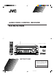
AUDIO/VIDEO CONTROL RECEIVER RX-9010VBK MAIN ROOM SUB ROOM STANDBY ON MAIN ROOM SUB ROOM TV/CATV/DBS ON/OFF ON/OFF DVD POWER VCR1 POWER DVD MULTI PHONO VCR 1 VCR 2 TAPE/MD CDR TV/DBS VIDEO FM/AM USB AUDIO ANALOG/DIGITAL CD EFFECT L—BALANCE—R INPUT 1 2 3 SOUND CENTER SUBWFR ROOM SIZE 4 5 6 LEVEL+ REAR·L REAR·R LIVENESS 7 8 LEVEL– TEST RX-9010V 9 AUDIO/VIDEO CONTROL RECEIVER CENTER TONE DIGITAL EQ 10 0 +10 RETURN FM MODE 100+ SURROUND DSP ON/OFF MODE
Warnings, Cautions and Others/ Mises en garde, précautions et indications diverses CAUTION RISK OF ELECTRIC SHOCK DO NOT OPEN CAUTION: TO REDUCE THE RISK OF ELECTRIC SHOCK. DO NOT REMOVE COVER (OR BACK) NO USER SERVICEABLE PARTS INSIDE. REFER SERVICING TO QUALIFIED SERVICE PERSONNEL.
For Canada/pour Le Canada For the main unit / Pour l’appareil principal THIS DIGITAL APPARATUS DOES NOT EXCEED THE CLASS B LIMITS FOR RADIO NOISE EMISSIONS FROM DIGITAL APPARATUS AS SET OUT IN THE INTERFERENCE-CAUSING EQUIPMENT STANDARD ENTITLED “DIGITAL APPARATUS,” ICES-003 OF THE DEPARTMENT OF COMMUNICATIONS.
Table of Contents Introduction ................................................ 2 Features ...................................................................................... 2 Precautions ................................................................................. 2 Parts Identification ...................................... 3 Getting Started ........................................... 5 Before Installation ......................................................................
Introduction We would like to thank you for purchasing one of our JVC products. Before operating this unit, read this manual carefully and thoroughly to obtain the best possible performance from your unit, and retain this manual for future reference. Features Precautions Dolby Digital Decoder Incorporated You can enjoy Dolby Digital, one of the most advanced home theater sound systems available.
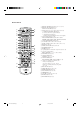
Parts Identification Refer to the pages in parentheses for details.
Remote Control 1 2 3 a b 4 STANDBY MAIN ROOM SUB ROOM MAIN ROOM SUB ROOM TV/CATV/DBS ON/OFF ON/OFF MAIN ROOM @ # SUB ROOM DVD DVD MULTI PHONO CD VCR 1 VCR 2 TAPE/MD CDR TV/DBS VIDEO FM/AM USB AUDIO L—BALANCE—R EFFECT INPUT 1 2 3 SOUND CENTER SUBWFR ROOM SIZE 4 5 6 LEVEL+ REAR•L REAR•R LIVENESS 7/P 8 9 6 7 8 9 0 - ON VCR1 POWER c ANALOG/DIGITAL 5 POWER LEVEL– TEST DIGITAL EQ CENTER TONE 10 0 RETURN FM MODE 100+ SURROUND DSP BASS BOOST ON/OFF +10 MOD
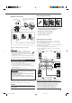
Getting Started This section explains how to connect audio/video components and speakers to the receiver, and how to connect the power supply. Before Installation General Connecting the FM and AM Antennas FM Antenna Connections • Be sure your hands are dry. • Turn the power off to all components. • Read the manuals supplied with the components you are going to connect.
Basic connecting procedure AM Antenna Connections Snap the tabs on the loop into the slots of the base to assemble the AM loop. ANTENNA FM 75 COAXIAL RIG RIG HT LE AM LOOP AM EXT AM Loop Antenna 4 3 2 1 RIG HT LE FT HT LE FT FT 1 Cut, twist and remove the insulation at the end of each speaker signal cable (not supplied). 2 Turn the knob counterclockwise. 1 2 3 3 Insert the speaker signal cable. 4 Turn the knob clockwise.
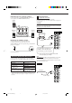
Connecting the rear and center speakers Connect rear speakers to the REAR SPEAKERS terminals and a center speaker to the CENTER SPEAKER terminals. Center speaker Analog Connections Audio component connections Use the cables with RCA pin plugs (not supplied). Connect the white plug to the audio left jack, and the red plug to the audio right jack.
Cassette deck or MD recorder Cassette deck To audio input To audio output RIGHT AUDIO LEFT Video component connections Use the cables with RCA pin plugs (not supplied). Connect the white plug to the audio left jack, the red plug to the audio right jack, and the yellow plug to the video jack. • If your video components have S-video (Y/C-separation) and/or component video (Y, PB/CB, PR/CR) jacks, connect them using an S-video cable (not supplied) and/or component video cable (not supplied).
TV and/or DBS tuner Video camera The VIDEO input jacks on the front panel are convenient when connecting and disconnecting the equipment frequently. When connecting the TV to the AUDIO jacks (TV SOUND/DBS), DO NOT connect the TV’s video output to these video input jacks.
Notes: Digital Connections This receiver is equipped with four DIGITAL IN terminals — one digital coaxial terminal and three digital optical terminals — and one DIGITAL OUT terminal. IMPORTANT: • When connecting the DVD player, digital TV broadcast tuner or DBS tuner using the digital terminals, you also need to connect it to the video terminal on the rear. Without connecting it to the video terminal, you can view no playback picture.
USB Connection This receiver is equipped with a USB terminal on the front panel. You can connect your PC to this terminal and enjoy sound reproduced through your PC. When you connect your PC for the first time, follow the procedure below. • Remember you cannot send any signal or data to your PC from this receiver. 5. Check if the drivers are correctly installed. 1. Open the Control Panel on your PC: Select [Start] = [Settings] = [Control Panel] 2.
Setting Up the RF Rod Antenna The remote control supplied for this receiver can transmit RF (Radio Frequency) signal. The RF rod antenna can receive the RF signals emitted from the remote control. So, with the RF rod antenna connected, you can operate the receiver at a distance of up to 50 feet (15 m) using the remote control. However, if the antenna cannot receive signals stably, you cannot operate the receiver correctly.
Connecting the Power Cord Before plugging the receiver into an AC outlet, make sure that all connections have been made. Putting Batteries in the Remote Control Before using the remote control, put two supplied batteries first. Plug the power cord into an AC outlet. 1. On the back of the remote control, remove the battery cover. Keep the power cord away from the connecting cables and the antenna. The power cord may cause noise or screen interference.
Multi-room Operations Before operating this receiver any further, be familiar with this Multi-room function. This function enables you to listen to different sources in two different places (we call these two places “main room” and “sub-room”) by using this receiver only. This section explains only required speaker connections, the concept, and basic operations of the Multi-room function. For more detailed operations, see the respective pages in this manual.
Basic Operating Procedure for Main Room From the remote control: 1. Set MAIN ROOM/SUB ROOM selector to “MAIN ROOM.” On the front panel: 1. Press POWER. The STANDBY lamp on the front panel goes off, and the MAIN ROOM indicator lights on the display. • For more details, “Turning the Power On and Off (Standby)” on page 17. STANDBY POWER MAIN ROOM Now the buttons and controls on the remote control work for the main room operations. 2. Press AUDIO POWER ON.
Basic Operating Procedure for Sub-Room The sources and functions available for the sub-room operations are limited. For more details on the sub-room operations, see “Sub-Room Operations” on pages 23 to 26. 5. Turn MASTER VOLUME to adjust the volume level of the sound from the front speakers in the sub-room. MASTER VOLUME On the front panel: 1. Press POWER. STANDBY The STANDBY lamp on the front panel POWER goes off, and the MAIN ROOM indicator lights on the display.
Main Room Basic Operations This section explains only the operations commonly used when you play any sound source in the main room. See pages 23 for the sub-room operations. You can use "On-screen Menu" for most of the main room operations. For details, see page 50. IMPORTANT: Turning the Power On and Off (Standby) Check to see if the proper indicator(s) and information appear on the display on the front panel before/while using the buttons and controls.
Canceling the Main Room Operations To stop the main room operations and sounds from the main room speakers, press MAIN ROOM ON/OFF. MAIN ROOM SUB ROOM MAIN ROOM ON /OFF ON/OFF On the front panel Selected source name and current Surround/DSP mode appear ANALOG DIGITAL The MAIN ROOM indicator on the display goes off, and the currently selected front speaker indicators also goes off (no sound will be heard in the main room). • You cannot use this receiver for the main room operations any more.
From the remote control: Notes: DVD DVD MULTI PHONO CD VCR 1 VCR 2 TAPE/MD CDR TV/DBS VIDEO FM/AM USB AUDIO • “S” is the monaural rear signal. It is automatically mixed down to “LS” and “RS.” • “LFE” signals are automatically mixed down to the other signals when you select the digital input mode. However, when you select “DVD MULTI,” this receiver reproduces the LFE signals only through subwoofer channel. * When you do not press SUBWOOFER OUT ON/OFF to deactivate the subwoofer.
On the front panel ONLY: When you have connected two pairs of the front speakers and set them to the main room, you can select which to use in the main room. To use the speakers connected to the FRONT 1 SPEAKERS terminals, press SPEAKERS ON/OFF 1 so that SPEAKERS 1 indicator lights up on the 1 display. (Make sure that the SPEAKERS 2 is not on the display.) On the front panel: The display changes to show the current setting.
Listening at Night — Midnight Mode Using the midnight mode, you can enjoy a powerful sound at night even at a low volume level. • You can do this setting for each source. You can boost the bass level. • You can do this setting for each source. Press BASS BOOST. Press MIDNIGHT MODE.
Selecting the Line Direct Function You can enjoy the sound closer to original source by skipping the sound adjustments such as Digital Equalization and Midnight Mode. Only the volume level and Bass Boost are adjustable when the Line Direct function is turned on. • You can do this setting for each source. Press LINE DIRECT. The LINE DIRECT lamp on the front panel button lights up.
Sub-Room Operations This section explains only the operations used when you play any sound source in the sub-room. See pages 17 for the main room operations. IMPORTANT: Check to see if the proper indicator(s) and information appear on the display on the front panel before/while using the buttons and controls. Turning the Power On and Off (Standby) and Selecting the Sub-room Operations For the sub-room operations: On the front panel: • The SUB ROOM indicator is lit.
From the remote control: Canceling the Sub-room Operations 1. Set MAIN ROOM/SUB ROOM selector to “SUB ROOM.” MAIN ROOM SUB ROOM Now the buttons on the remote control work for the sub-room operations. 2. Press AUDIO POWER ON. STANDBY ON The STANDBY lamp on the front panel goes off, and the SUB ROOM indicator lights up on the display (and the SPEAKERS SUB ROOM indicator also lights up on the display if it has been activated).
Selecting the Sub-room Source to Play Press one of the source selecting buttons. The lamp on the front panel button for selected source lights up. • The selected source name also appears on the display. • When the source name of TV SOUND/DBS is assigned to “TV SOUND,” TV SOUND/DBS buttons does not work. To change the source name, see “Changing the Source Name” on page 33.
Activating the Sub-room Front Speakers This section is not for the persons who connect the sub-room front speakers to the SUB ROOM PRE OUT jacks using another amplifier (see page 14). Operating the Playback Source for the Sub-room • When you select “FM” or “AM” as the sub-room source, you can do the following: – Tune into any station frequency manually (see page 35). Before you start, remember... • When shipped from the factory, both pairs of the front speakers have been set to be used in the main room.
Basic Settings Some of the following settings are required after connecting and positioning your speakers, while others will make operations easier. • You can use “On-screen Menu” for most of the main room operations. For details, see page 50. The following operations are only possible while the receiver is ready for the main room operations.
From the remote control: SOUND Adjusting the Subwoofer Output Level 1. Press SOUND. The 10 keys are activated for sound adjustments. 2. Press BALANCE R or BALANCE L to adjust the balance. L—BALANCE—R • Pressing BALANCE R decreases the left 1 2 channel output (from R –21 to CENTER, from CENTER to L –21). • Pressing BALANCE L decreases the right channel output (from L –21 to CENTER, from CENTER to R –21).
Setting the Speakers for a Surround Field To obtain the best possible surround sound of the Surround and DSP modes, you have to register the information about the speakers arrangement after all connections are completed. • This function is applied only to the main room sources. Before you start, remember.... • There is a time limit in doing the following steps. If the setting is canceled before you finish, start from step 1 again.
Low Frequency Effect Attenuator Setting Center speaker Front speaker Front speaker If the bass sound is distorted while playing back a source using Dolby Digital or DTS Digital Surround, follow the procedure below. On the front panel ONLY: 3.0 m 2.7 m 2.4 m 2.1 m 1. Press SETTING repeatedly until “LFE ATT” (Low Frequency Effect Attenuator) appears on the display. The display changes to show the current setting. 2. Press CONTROL UP 5/DOWN ∞ to select the low frequency effect attenuator level. EX.
To set the DIGITAL 2/3/4 terminals: 1. Press SETTING until DIGITAL 2/3/4 terminals setting appears on the display. SETTING When you have connected digital source components using the digital terminals (see page 10), you need to change the input mode for these components to the appropriate digital input mode correctly — DGTL AUTO, DGTL DTS, or DGTL D.D. The display changes to show the current settings for the DIGITAL 2/3/4 terminals.
When playing a software encoded with the Dolby Digital or DTS Digital Surround, the following symptoms may occur: • Sound does not come out at the beginning of playback. • Noise comes out while using the searching for or skipping chapters or tracks. In this case press CONTROL UP 5/DOWN ∞ CONTROL to select “DGTL D.D” or “DGTL DTS” DOWN UP while “DGTL AUTO” still remains on the display. • Each time you press the button, the input mode changes as follows: DGTL AUTO (Digital) DGTL D.
Changing the Source Name When you have connected an MD recorder to the TAPE/MD jacks or the DBS tuner to the TV SOUND/DBS jacks on the rear panel, change the source name which will be shown on the display when you select the MD recorder or DBS tuner as the source. • When you select DBS as a source for the sub-room, you cannot change the source name. On the front panel ONLY: When changing the source name from “TAPE” to “MD”: • Press and hold SOURCE NAME (TAPE/MD) until “ASSGN. MD” appears on the display.
Basic Setting and Adjustment — Auto Memory Without any setting required, this receiver stores different sound settings for each different playing source automatically whenever you do the following: • Turning on the power (see page 17) • Changing the source to play (see page 18) • Changing the source name (see page 33) So, you do not have to change the sound settings next time you select the same source. The stored settings for the selected source are automatically recalled.
Receiving Radio Broadcasts You can browse through all the stations or use the preset function to go immediately to a particular station. • You can use “On-screen Menu” for most of the main room operations. For details, see page 50. Indicates the functions YOU CAN ALSO USE when the receiver is ready for the sub-room operations. IMPORTANT: Check to see if the proper indicator(s) and information(s) appear on the display on the front panel before/while using the buttons and controls.
4. Press MEMORY again while the selected channel number is flashing on the display. MEMORY The selected channel number stops flashing. The station is assigned to the selected channel number. ANALOG L AUTO MUTING TUNED STEREO R Selecting the FM Reception Mode When an FM stereo broadcast is hard to receive or noisy You can change the FM reception mode while receiving an FM broadcast. • You can store the FM reception mode for each preset station. MAIN ROOM SPEAKERS Press FM MODE. VOLUME 1 5.
Creating a Surround Field in the Main Room The built-in Surround Processor provides Surround mode and four types of the DSP (Digital Signal Processor) mode — DAP (Digital Acoustic Processor) mode, 5 CH/4 CH Stereo mode, 3D-PHONIC mode and HEADPHONE DSP mode. With this receiver, you can use a Surround mode and a DSP mode at the same time. Once you have adjusted Surround and/or DSP modes, the adjustments done for each source are memorized. • You can use “On-screen Menu” for most of the main room operations.
3D-PHONIC modes The 3D-PHONIC mode gives you such a nearly surround effect as is reproduced through the Dolby Surround decoder, which is widely used to reproduce sounds with a feeling of movement like those experienced in movie theaters. The 3D-PHONIC mode is the result of research on sound localization technology carried out at JVC for many years. This mode can be used when the front speakers are connected to this receiver (without respect to the rear/center speaker connection).
Available DSP Modes According to the Speaker Arrangement Available DSP modes will vary depending on how many speakers are used with this receiver. Make sure that you have set the speaker information correctly (see page 29).
Adjusting the Surround Modes Once you have adjusted the Surround modes, the adjustment is memorized for each source. You can also use a Surround mode with a DAP mode (see page 43). IMPORTANT: Check to see if the proper indicator(s) and information appear on the display on the front panel before/while using the buttons and controls. For the main room operations: • The MAIN ROOM indicator is lit. • The source name for the sub-room is not lit on the display.
9. Press CENTER TONE to select the center tone level you want. CENTER TONE +10 100+ The center tone adjustment affects the midfrequency range, which the human voice is mostly made up of. • Each time you press the button, the display changes to show the following: CTR TONE 1 CTR TONE 3 CTR TONE 2 (Softer) (Soft) (Flat) 4. Adjust the center tone. EFFECT 1) Press EFFECT repeatedly until “CTR TONE” appears on the display. The display changes to show the current setting.
Before you start, remember... • Make sure that you have set the speaker information correctly (see page 29). • When the SUB ROOM and SPEAKERS SUB ROOM indicators are lit on the display, you can only use 3D-PHONIC modes for the main room source. • There is a time limit in doing the following steps. If the setting is canceled before you finish, start from step 2 again. • You cannot adjust the center speaker output level when you have set “CTR SPK” to “NONE” (see page 29).
From the remote control: 1. Press DSP MODE repeatedly until the DSP MODE DAP mode you want to adjust — THEATER 1, THEATER 2, HALL 1, HALL 2, LIVE CLUB, DANCE CLUB, or PAVILION — appears on the display. The DSP MODE lamp on the front panel button lights up, and the DSP indicator also lights up on the display. • When you have set “REAR SPK” to “NONE,” the 3DPHONIC indicator also lights up. 2. Press SOUND. SOUND The 10 keys are activated for sound adjustments. 3. Select the speaker you want to adjust.
Before you start, remember... • Make sure that you have set the speaker information correctly (see page 29). • This function does not work when you activate the sub-room. • There is a time limit in doing the following steps. If the setting is canceled before you finish, start from step 4 again. • You cannot adjust the rear speaker output levels when you have set “REAR SPK” to “NONE.” See page 29. • You cannot adjust the center speaker output level and center tone when you have set “CTR SPK” to “NONE.
13.Press LIVENESS to adjust the liveness. LIVENESS 9 • Each time you press the button, the display changes to show the following: LIVENESS 1 LIVENESS 2 LIVENESS 5 LIVENESS 3 LIVENESS 4 As the number increases, the attenuation level of reflections over time decreases so that acoustics change from “Dead” to “Live.” (Normally set it to “LIVENESS 3.”) 5. Adjust the center tone. (Softer) You can also use the buttons on the front panel to adjust the sound with a Surround mode and a DAP mode.
8. Adjust the liveness. EFFECT 1) Press EFFECT repeatedly until “LIVENESS” appears on the display. The display changes to show the current setting. 2) Press CONTROL UP 5/DOWN ∞ to select the liveness level you want.
From the remote control: DSP 1. Press DSP MODE repeatedly until “5CH STEREO*” appears on the display. Once you have adjusted the 3D-PHONIC modes, the adjustment is memorized for each source. The DSP MODE lamp on the front panel button lights up, and the DSP indicator also lights up on the display. * “4CH STEREO” appears on the display when you have set “CTR SPK” to “NONE.” (See page 29.) SOUND 2. Press SOUND. 3. Select the speaker you want to adjust.
On the front panel: From the remote control: 1. Press DSP MODE repeatedly until “3D ACTION” or “3D DIGITAL” appears on the display. DSP MODE The DSP MODE lamp on the front panel button lights up, and the 3D-PHONIC and DSP indicators also light up on the display. 1. Press DSP MODE repeatedly until “3D ACTION” or “3D DIGITAL” appears on the display. The DSP MODE lamp on the front panel button lights up, and the 3D-PHONIC and DSP indicators also light up on the display. LEVEL ADJUST 2.
Using the DVD MULTI Playback Mode This receiver provides the DVD MULTI playback mode for reproducing the analog discrete output mode of the DVD player. Before playing back a DVD, refer also to the manual supplied for the DVD player. • You can use “On-screen Menu” for most of the main room operations. For details, see page 50. The following operations are only possible while the receiver is ready for the main room operations, and are only used for the main room source — DVD MULTI.
Using the On-Screen Menus You use the black-and-white color Menus on the TV screen to control the receiver. To use this function, you need to connect the TV to the MONITOR OUT jack on the rear panel (see page 9), and set the TV’s input mode to the proper position to which the receiver is connected. • When the TV’s input mode is incorrect; for example, a different video input or TV tuner mode is selected, you cannot show the Menus on the TV screen.
For Surround modes and Surround mode with DAP mode: “TEST TONE”: Output a test tone. “L/R BALANCE”: Adjust the right and left balance of the front speakers. “CENTER LEVEL”: Adjust the center speaker output level. * “REAR L LEVEL”: Adjust the left rear speaker output level. ** “REAR R LEVEL”: Adjust the right rear speaker output level. ** “SUBWFR LEVEL”: Adjust the subwoofer output level. *** For DAP mode: “L/R BALANCE”: Adjust the right and left balance of the front speakers.
7. Press % / fi to move to “EFFECT ADJUST,” then press @ / #. The EFFECT LEVEL menu appears. SOUND CONTROL DIGITAL EQ LEVEL ADJUST EFFECT ADJUST MIDNIGHT MODE: NORMAL INPUT ATT : NORMAL LINE DIRECT: OFF BASS BOOST : OFF SUBWOOFER : ON :ENTER 8. Press % / fi to move to the item you want to adjust, then press @ / #. EFFECT ADJUST EFFECT LEVEL: ROOM SIZE : LIVENESS : CENTER TONE : On these adjustment menus, you can do the following.
Selecting the Line Direct Function (Also see page 22) Activating the Subwoofer Sound (Also see page 21) 1. Press MENU. 1. Press MENU. The MENU appears on the TV. • Pressing one of the % / fi / @ / # buttons also displays the MENU. 2. Press % / fi to move to “SOUND CONTROL,” then press @ / #. 2. Press % / fi to move to “SOUND CONTROL,” then press @ / #. The SOUND CONTROL menu appears. The SOUND CONTROL menu appears. 3. Press % / fi to move to “LINE DIRECT.” 4.
Storing the Preset Stations (Also see page 35) 1. Press MENU. The MENU appears on the TV. • Pressing one of the % / fi / @ / # buttons also displays the MENU. 2. Press % / fi to move to “TUNER CONTROL,” then press @ / #. The TUNER CONTROL menu appears. 3. Tune into a station on the TUNER CONTROL menu, referring to “Operating the Tuner” on page 53. 4. Press % / fi to move to “PRESET MEMORY,” then press @ / #. TUNER CONTROL BAND PRESET CH FREQUENCY FM MODE : FM : 20 : 87.
COMPU LINK Remote Control System The COMPU LINK remote control system allows you to operate JVC audio components through this receiver. To use this remote control system, you need to connect JVC audio components through the COMPU LINK (SYNCHRO) jacks (see below) in addition to the connections using cables with RCA pin plugs (see pages 7 and 8). • Make sure that the AC power cords of these components are unplugged before connection. Plug the AC power cords only after all connections are complete.
Automatic Power On/Off (Standby): only possible with the COMPU LINK-3 and COMPU LINK--4 connection Synchronized Recording This operation is only possible while the receiver is ready for the main room operations.
TEXT COMPU LINK Remote Control System The TEXT COMPU LINK remote control system has been developed to deal with the disc information recorded in the CD Text* and MDs. Using this information in the discs, you can operate the CD player or MD recorder equipped with the TEXT COMPU LINK remote control system through the receiver. The following operations are only possible while the receiver is ready for the main room operations, and are used for the main room sources.
Disc Information screen OPERATIONS: To use this remote control system, you need to connect the TV to the MONITOR OUT jack on the rear panel (see page 9), and set the TV’s input mode to the proper position to which the receiver is connected. Make sure you have connected the CD player or MD recorder equipped with the TEXT COMPU LINK remote control system. If not, you cannot use the following functions.
Searching for a Disc (Only for the CD player) Search for a disc by its performer: 1. Press TEXT DISPLAY while “CD” is selected as the source. The Disc Information screen appears on the TV. 2. Press % / fi to move SET. to “SEARCH,” then press The DISC SEARCH screen appears . 3. Press % / fi to move to “PERFORMER,” then press SET. The PERFORMER SEARCH screen appears. 4. Press % / fi / @ / # to in front of the move first character of the performer you want to search for, then press SET.
Search for a disc by its genre: 1. Press TEXT DISPLAY while “CD” is selected as the source. The Disc Information screen appears on the TV. 2. Press % / fi to move press SET. to “SEARCH,” then The DISC SEARCH screen appears. 3. Press % / fi to move to “GENRE,” then press SET. Note: The GENRE SEARCH screen appears. 4. Press % / fi to move search for, then press SET.
For the MD recorder: 4. Repeat step 3 until you finish putting a performer name (up to 32 characters). To insert a space, press % / fi / @ / # to move , then press SET. to To correct an incorrect character: 1) Press % / fi / @ / # to move to + or =, then press SET until the incorrect character is selected. 2) Press % / fi / @ / # to move to , then press SET to erase the character. in front of the correct 3) Press % / fi / @ / # to move character, then press SET to enter the correct character. 1.
AV COMPU LINK Remote Control System This receiver is equipped with the AV COMPU LINK-III. The AV COMPU LINK remote control system allows you to operate JVC video components (TV, VCR, and DVD player) through the receiver. To use this remote control system, you need to connect the video components you want to operate, following the procedure below. 1.
CONNECTIONS 3: Video Cable Connection This receiver is equipped with three types of the video terminals — S-video, composite video, or component video, and the signals coming into this receiver through one type of video terminals can output only through the same type of the terminal.
One-Touch DVD Play Simply by starting playback on the DVD player, you can enjoy the DVD playback without setting other switches manually. When you press PLAY on the remote control supplied with this receiver for operating the DVD player, the receiver automatically turns on and changes the main room source or sub-room source (depending on MAIN ROOM/SUB ROOM selector setting on the remote control) to the appropriate input — “DVD,” or “DVD MULTI” as the main room source, and “DVD” as the sub-room source.
Operating JVC’s Audio/Video Components You can operate JVC’s audio and video components with this receiver’s remote control, since control signals for JVC components are preset in the remote control.
CD player-changer After selecting CDDSC by pressing CONTROL repeatedly, you can perform the following operations on a CD player-changer: PLAY: Starts playing. 4: Returns to the beginning of the current (or previous) track. ¢: Skips to the beginning of the next track. STOP: Stops playing. PAUSE: Pauses playing. To release it, press PLAY. 1 – 6, 7/P: Selects the number of a disc installed in a CD player-changer.
VCR (VCR connected to the VCR 1 jacks) Operating Video Components You can always perform the following operations: VCR 1 POWER: Turns on or off the VCR 1. IMPORTANT: To operate JVC’s video components using this remote control: • You need to connect JVC video components through the AV COMPU LINK jacks (see page 62) in addition to the connections using cables with RCA pin plugs (see pages 8 and 9). • Some JVC VCRs can accept two types of the control signals — remote codes “A” and “B.
Operating Other Manufacturers’ Equipment This remote control supplied with the receiver can transmit control signals for other manufacturers’ VCRs, TVs, CATV converters, DBS tuners, DVD players ,and CD players. By changing the transmittable signals from preset ones to the other manufacturers’, you can operate the other manufacturer’s components using this remote control. When operating the other manufacturers’ components, refer also to the manuals supplied with them.
To change the transmittable signals for operating a CATV converter and DBS tuner 1. Set TV/CATV/DBS selector to “CATV/DBS.” 2. Press and hold TV/CATV/DBS POWER. 4. Release VCR 1 POWER. The following button can be used for operating the VCR : VCR 1 POWER: After pressing VCR 1, you can perform the following operations on the VCR: CHANNEL +/–: 3. Press TV/DBS. 1 – 10, 0, 100+ (+10): 4. Enter manufacturer’s code using buttons 1–9, and 0. See pages 70 and 71 to find the code. 5. Release TV/CATV/DBS POWER.
Manufactures' codes for TV After pressing DVD MENU (only for the main room operations), these buttons can be used for the DVD menu operations. Manufacturer TEXT DISPLAY MENU SET DVD MENU EXIT Note: For detailed menu operations, refer to the instructions supplied with the discs or the DVD player. JVC FISHER HITACHI MAGNAVOX METS MITSUBISHI PANASONIC PHILIPS QUELLE Note: Refer to the manual supplied with your DVD player. 5. Try to operate your DVD player by pressing one of the above buttons.
Manufactures' codes for CATV converter Manufacturer Manufactures' codes for DVD player Manufacturer Codes JVC DENON PANASONIC PHILIPS PIONEER RCA SAMSUNG SONY TOSHIBA YAMAHA GENERAL INSTRUMENT 29 HAMLIN/RE 01, 02, 03, 04, 05 JERROLD/G 06, 07, 08, 09, 10, 11, 12, 13, 14 OAK 15, 16, 17 PANASONIC 18, 19, 20 PIONEER 21, 22 SCIENTIFF 23, 24, 25 TOCOM 26 ZENITH 27, 28 Codes 00*, 02 01 03 13 04, 05, 06 07 08 09 10 11, 12 *This figure is set to the remote control as the initial JVC cord.
Troubleshooting Use this chart to help you solve daily operational problems. If there is any problem you cannot solve, contact your JVC service center. PROBLEM SOLUTION POSSIBLE CAUSE The display does not light up. The power cord is not plugged in. Plug the power cord into an AC outlet. (See page 13.) The buttons and controls on the front panel do not work. The Multi-room function is not set correctly. • Press MAIN ROOM ON/OFF for the main room operations.
PROBLEM Continuous hiss or buzzing during FM reception. POSSIBLE CAUSE SOLUTION Incoming signal is too weak. Connect an outdoor FM antenna or contact your dealer. (See page 5.) The station is too far away. Select a new station. An incorrect antenna is used. Check with your dealer to be sure you have the correct antenna. Antennas are not connected properly. Check connections. (See page 5.) Occasional cracking noise during FM reception. Ignition noise from automobiles.
Designs & specifications are subject to change without notice. Specifications Amplifier Output Power At Stereo operation: Front channels: 120 W per channel, min. RMS, driven into 8 Ω, 20 Hz to 20 kHz with no more than 0.02% total harmonic distortion. 120 W per channel, min. RMS, driven into 4 Ω, 20 Hz to 20 kHz with no more than 0.08% total harmonic distortion. At Surround operation: Front channels: 100 W per channel, min. RMS, driven into 8 Ω at 1 kHz with no more than 0.8% total harmonic distortion.
QUALITY SERVICE HOW TO LOCATE YOUR JVC SERVICE CENTER TOLL FREE : 1-800-537-5722 http://www.jvcservice.com Dear customer: In order to receive the most satisfaction from your purchase, read the instruction booklet before operating the unit. In the event that repair is necessary, or for the address nearest your location, please refer to the factory service center list below or within the Continental United States, Call 1-800-537-5722 for your authorized servicer.
LIMITED WARRANTY AUDIO-2 JVC COMPANY OF AMERICA warrants this product and all parts thereof, except as set forth below ONLY TO THE ORIGINAL PURCHASER AT RETAIL to be FREE FROM DEFECTIVE MATERIAL AND WORKMANSHIP from the date of original retail purchase for the period as shown below. (“The Warranty Period.”) PARTS LABOR 2YR 2YR THIS LIMITED WARRANTY IS VALID ONLY IN THE FIFTY(50) UNITED STATES, THE DISTRICT OF COLUMBIA AND IN COMMONWEALTH OF PUERTO RICO.
VICTOR COMPANY OF JAPAN, LIMITED V EN RX-9010VBK[J]cover_f J 2 01.2.