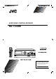
AUDIO/VIDEO CONTROL RECEIVER RX-772VBK RM-SR772U REMOTE CONTROL TV/CATV /SAT POWER VCR POWER SLEEP VIDEO VCR TAPE CD PHONO TVSOUND FM/AM ONE TOUCH DELAY OPERATION CNTR 1 CD DISC AUDIO POWER 2 3 TEST REAR 4 5 7/P 8 6 CD TRACK 9 SOUND SEA MODE CONTROL RX-772V SURR MODE 0 10 AUDIO/TV /VCR MASTER VOLUME AUDIO/VIDEO CONTROL RECEIVER VIDEO VCR TV SOUND FM AM CD PHONO TAPE +10 RETURN FM MODE/MUTE 100+ ONE TOUCH OPERATION E VOLUM – + SOURCE CATV /SAT L CHANNE E S
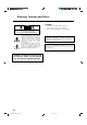
Warnings, Cautions and Others CAUTION RISK OF ELECTRIC SHOCK DO NOT OPEN CAUTION To reduce the risk of electrical shocks, fire, etc.: 1. Do not remove screws, covers or cabinet. 2. Do not expose this appliance to rain or moisture. CAUTION: TO REDUCE THE RISK OF ELECTRIC SHOCK. DO NOT REMOVE COVER (OR BACK) NO USER SERVICEABLE PARTS INSIDE. REFER SERVICING TO QUALIFIED SERVICE PERSONNEL.
Once you have found the best Surround settings for your listening room, note them in the table below for future reference (even though the receiver memorizes the settings until you change them). For actual setting procedures, see pages 24 to 30.
Table of Contents Getting Started ........................................................................................................................... 2 Before Installation .................................................................................................................... 2 Checking the Supplied Accessories ......................................................................................... 2 Switches, Buttons and Controls ........................................................
Getting Started This section explains how to connect audio/video components and speakers to the receiver, and how to connect the power supply. Before Installation General • Be sure your hands are dry. • Turn the power off to all components. • Read the manuals supplied with the components you are going to connect. Locations • Install the receiver in a location that is level and protected from moisture. • The temperature around the receiver must be between 23˚ and 95˚ F (–5˚ and 35˚ C).
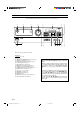
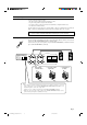
Switches, Buttons and Controls Become familiar with the main switches and controls on your receiver before use. 1 2 RX-772V 3 4 5 6 7 8 y u MASTER VOLUME AUDIO/VIDEO CONTROL RECEIVER VIDEO ONE TOUCH OPERATION – VCR TV SOUND FM AM CD PHONO TAPE + SOURCE SURROUND MODE SEA MODE SURROUND ADJUST SEA ADJUST MEMORY SETTING TUNER MEMORY STANDBY SPEAKERS 1 PHONES 2 POWER SEA Graphic Equalizer 9 p q _ON —OFF w e r t Refer to the pages in parentheses for details.
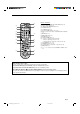
Remote Control j RM-SR772U REMOTE CONTROL i o ; a s d TV/CATV /SAT POWER VCR POWER SLEEP AUDIO POWER VIDEO VCR TAPE TVSOUND FM/AM CD ONE TOUCH DELAY OPERATION PHONO CNTR 1 CD DISC 2 TEST 3 i o ; a s d f REAR 4 5 6 7/P 8 9 CD TRACK SOUND SEA MODE CONTROL l SURR MODE 10 0 +10 RETURN FM MODE/MUTE AUDIO/TV /VCR 100+ ME VOLU f k Remote Control Unit / g h j k l CATV /SAT HANNEL C z TE g MU 4 W / RE PLAY FF / ¢ STOP PAUSE REC x ME TV VOLU IDEO TV/V CONTRO
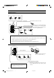
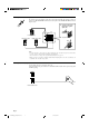
Connecting the FM and AM Antennas FM Antenna Connections 1 3 2 FM Antenna Extend the FM wire antenna horizontally. ANTENNA 4 If reception is poor, connect the outside antenna. Before attaching a 75-ohm coaxial cable (the kind with a round wire going to an outside antenna), disconnect the supplied FM antenna. Outside FM Antenna Wire FM 75 FM GND 2 1 GND 3 7/16 in. AM LOOP AM EXT 13/16 in. (10 mm) (20 mm) How to strip the 75-ohm coaxial cable and connect it to the FM terminals 1.
Connecting the Speakers You can connect the following speakers: • Two pairs of front speakers to produce normal stereo sound. • One pair of rear speakers to enjoy the surround effect. • One center speaker to produce more effective surround effect (to emphasize human voices). • One subwoofer to enhance the bass. For each speaker (except for subwoofer), connect the black (–) and red (+) terminals on the rear panel to the black (–) and red (+) terminals marked on the speakers.
Connecting the rear and center speakers Cut, twist and remove the insulation at the end of each speaker signal cable first, and then, connect rear speakers to the REAR SPEAKERS terminals and a center speaker to the CENTER SPEAKER terminals by using the cables. 1 CENTER SPEAKER Open the terminal and then insert the speaker signal cable. REAR SPEAKERS RIGHT LEFT Center speaker Left rear speaker 2 Right rear speaker Close the terminal.
Connecting Audio/Video Components You can connect the following audio/video components to this receiver using cables with RCA pin plugs (not supplied). Refer also to the manuals supplied with your components. If you want to connect a component not listed in the table below, refer to the manual supplied with it.
Video component connections GND AUDIO RIGHT LEFT PHONO To video input VCR To audio input TV CD VHS To audio output OUT (REC) VCR To video output To audio output Video disc player VCR IN (PLAY) VIDEO To video output OUT (REC) TV SOUND OUT (REC) IN (PLAY) To video input (See note below.
Connecting the Power Cord Before plugging the receiver into an AC outlet, make sure that all connections have been made. When the power cord is connected, the STANDBY lamp above the POWER button lights up. Keep the power cord away from the connecting cables for the TV, VCR, and antenna. The power cord may cause noise or screen interference. We recommend that you use a coaxial cable to connect the antenna, since it is well-shielded against interference.
Basic Operations The following operations are commonly used when you play any sound source. IMPORTANT When using the Remote Control, check to see if its remote control mode selector is set to the correct position: To operate an audio system, TV, and VCR, set it to the “AUDIO/TV/VCR” position. To operate a CATV converter and satellite tuner, set it to the “CATV/SAT” position. AUDIO/TV /VCR CATV /SAT Turning the Power On and Off On the front panel: STANDBY To turn on the power, press POWER.
From the remote control: VIDEO VCR TAPE CD PHONO TVSOUND FM/AM Press one of the source selecting buttons you want. VIDEO Play back a video source on the video component connected to the VIDEO jacks. VCR Play back a video source on the video component connected to the VCR jacks. TV SOUND Listen to TV sounds. FM/AM* Listen to the radio. Each time you press the button, the band alternates between FM and AM. TAPE* Listen to a cassette tape connected to the TAPE jacks. CD* Listen to a CD.
Listening with Headphones A standard pair of headphones can be connected to the PHONES jack on the front panel. To listen with only headphones, press both SPEAKERS 1 and 2 to set them in the —OFF position. No sound comes out of the front speakers. CAUTION: Be sure to turn down the volume before connecting or putting on headphones, as high volume can damage both the headphones and your hearing.
Basic Settings Some of the following settings are required after connecting and positioning your speakers in your listening room, while others will make operations easier. See also page 31. MENU Adjusting the Front Speaker Output Balance If the sounds you hear from the front right and left speakers are unequal, you can adjust the speaker output balance. On the front panel only: SETTING 1. Press SETTING so that the Control % / fi / @ / # buttons work for adjusting the balance.
See also page 32. MENU Using the Sleep Timer Using the Sleep Timer, you can fall asleep to music and know the receiver will turn off by itself rather than play all night. On the front panel: 1. Press SETTING so that the Control % / fi / @ / # buttons work for setting the Sleep Timer The lamp next to the button lights up. SETTING 2. Press Control % / fi until “” appears on the display. 3. Press Control @ / # to set the shut-off time.
See also page 32. MENU Selecting the Center Speaker Size You can register the information on the center speaker after all connections are completed. If you do this registration first, you do not have to adjust the center speaker mode when you want to activate the Dolby surround. However, to register the information, first you have to set the surround mode either to “PROLOGIC” or “3CHLOGIC.” (You cannot select the center speaker size when the surround mode is “SURR OFF” or “HALL.
See also page 32. MENU Using Visual Confirmation When you operate the receiver, you can see what you are doing, by showing it on the TV screen. To use this function, you need to connect the TV to the MONITOR OUT jack on the rear panel (see page 9), and set the TV’s input mode to the proper position to which the receiver is connected. When the TV’s input mode is for TV, you cannot see the on-screen display. On the front panel only: 1.
One Touch Operation This receiver can memorize the optimum sound settings for each playing source. About the One Touch Operation JVC’s One Touch Operation function is used to assign and store different sound settings for each different playing source. By using this function, you don’t have to change the settings every time you change the source. The stored settings for the newly selected source are automatically recalled.
Receiving Radio Broadcasts You can browse through all the stations or use the preset function to go immediately to a particular station. See also page 33. MENU Tuning in Stations Manually On the front panel only: TUNER 1. Press TUNER so that the Control % / fi / @ / # buttons work for tuner settings. The lamp next to the button lights up. MEMORY 2. Press Control % / fi until “” appears on the display. 3. Press Control @ / # to select the band.
CAUTION: Preset stations may be erased when power is cut off to the receiver, as when it is unplugged from the AC outlet or a power failure occurs. If the preset stations are lost, simply set the stations again. To tune in a preset station TUNER On the front panel: MEMORY 1. Press TUNER so that the Control % / fi / @ / # buttons work for tuner settings. The lamp next to the button lights up. 2. Press Control % / fi until “–PRESET+” appears on the display. 3.
See also page 33. MENU Assigning Names to Preset Stations You can assign a name of up to five characters to each preset station (from preset channel number 1 to 20). When a preset station is tuned in, its assigned name will appear on the display. On the front panel only: 1. Tune in a preset station (preset channel number 1 to 20). See page 20 for details. TUNER 2. Press MEMORY (next to the TUNER button). The preset channel number starts flashing.
Using the SEA Modes The SEA (Sound Effect Amplifier) modes give you control of the way your music sounds. Note: The SEA modes cannot be used for recording. See also page 33. MENU Selecting Your Favorite SEA Mode On the front panel: 1. Press SEA MODE so that the Control % / fi buttons work for selecting the SEA mode. The lamp next to the button lights up. SEA MODE 2. Press Control % / fi until the mode you want appears on the display.
See also page 33. MENU Creating Your Own SEA Mode You can adjust and store your own SEA adjustment into memory (USERMODE). On the front panel only: If you do not want to store your adjustment, but rather want to adjust the SEA temporarily, skip step 3 below. SEA ADJUST 1. Press SEA ADJUST so that the Control % / fi / @ / # buttons work for the SEA adjustment. The lamp next to the button lights up. MEMORY 2. Adjust the SEA frequency and its level.
Using the Surround Processor The built-in surround processor provides three types of surround programs — Dolby Pro Logic, Dolby 3Channel Logic, and JVC’s Hall Surround. What is surround? The sound heard in a concert hall or a movie theater consists of direct sound and indirect sound: early reflections and reflections from behind. The reflected sounds are always delayed by the distances of the ceiling and walls from the listener.
3. Press SURROUND ADJUST so that the Control % / fi / @ / # buttons work for the surround settings. The lamp next to the button lights up. SURROUND ADJUST 4. Press Control % / fi until “– REAR +” appears on the display. 5. Press Control @ / # to adjust the rear speaker output level. • Pressing Control @ decreases the output level up to –10 dB. • Pressing Control # increases the output level up to +10 dB. 6. Press Control % / fi until “–DELAY +” appears on the display. 7.
Speaker arrangements for Dolby Surround The following illustrations show how to obtain the optimum sound environment for various Dolby Surround settings. Try to find the speaker direction and location to create the optimum sound field. CASE 1 When you have added a center speaker and rear speakers Front Speaker TV Center Speaker Front Speaker In this case: 1. Select “PROLOGIC.” 2. Select “NORMAL” or “WIDE” for center mode.
See also page 34. MENU Preparing for Dolby Surround The receiver memorizes two sets of Dolby Surround adjustments; one for Pro Logic and the other for 3ch Logic. On the front panel: 1. Press SURROUND MODE so that the Control % / fi buttons work for selecting the surround modes. The lamp next to the button lights up. SURROUND MODE 2. Press Control % / fi until “PROLOGIC” or “3CHLOGIC” whichever you want appears on the display.
6. Press Control % / fi until “–DELAY +” appears on the display. 7. Press Control @ / # to adjust the delay time of the rear speaker output. Each time you press the button, the delay time changes as follows: DELAY 1 DELAY 2 DELAY 4 DELAY 3 DELAY 1: Select this when the distance from you to your rear speakers is greater than that to the front speakers. DELAY 2: Select this when the distance from you to your rear speakers is almost equal to that to the front speakers.
From the remote control: Note: If you want to use the remote control for adjusting the center mode and the center tone, use the menu function (see page 34). SOUND CONTROL 1. Press SOUND CONTROL. The remote control is activated for adjusting the sound. 2. Press SURR MODE until “PROLOGIC” or “3CHLOGIC” whichever you want appears on the display. The PRO LOGIC or 3CH LOGIC indicator (as well as the SURROUND indicator) also lights up.
See also page 34. MENU Using Dolby Surround Once you have set the Dolby Surround adjustments you can use the same adjustments every time you want to enjoy Dolby Surround. The receiver memorizes two sets of Dolby Surround adjustments; one for Pro Logic and the other for 3ch Logic. On the front panel: 1. Press SURROUND MODE so that the Control % / fi buttons work for selecting the surround modes. The lamp next to the button lights up. SURROUND MODE 2.
Using the On-Screen Display to Control the Receiver You can use the menu function on the TV screen to control the receiver. To use this function, you need to connect the TV to the MONITOR OUT jack on the rear panel (see page 9), and set the TV’s input mode to the appropriate position to which the receiver is connected. When the TV’s input mode is for TV, you cannot see the on-screen display.
Listening at Low Volume (Loudness) (Also see page 14) 1. Press MENU. The MAIN MENU appears on the TV. to “SETTING,” then press @ / #. 2. Press % / fi to move The SETTING menu appears. 3. Press % / fi to move SETTING menu to “LOUDNESS.” 4. Press @ / # to set the loudness function to “ON” or “OFF.” 5. When you finish, press MENU EXIT. The menu disappears from the TV. Using the Sleep Timer (Also see page 15) 1. Press MENU. The MAIN MENU appears on the TV. 2.
Operating the Tuner 1. Press MENU. The MAIN MENU appears on the TV. to “TUNER,” then press @ / #. 2. Press % / fi to move The TUNER menu appears. TUNER menu to the item you want to set or adjust, then press @ / #. 3. Press % / fi to move On the TUNER menu, you can do the following: “CH.”: Select a preset channel station. (See page 20) If you want to assign a name to a preset channel, see page 21. “BAND”: Select the band. (See page 19) “TUNING”: Tune in a station manually.
Selecting the Surround Modes (Also see pages 24) 1. Press MENU. The MAIN MENU appears on the TV. to “SURROUND,” then press @ / #. 2. Press % / fi to move The SURROUND MODE menu appears. 3. Press % / fi to move SURROUND MODE menu to one of the surround modes. If you want to adjust the selected mode, go to the following steps. 4. Press MENU. The MAIN MENU appears on the TV again. 5. Press % / fi to move to “SURROUND ADJUST,” then press @ / #.
COMPU LINK Remote Control System The COMPU LINK remote control system allows you to operate JVC audio components through the remote sensor on the receiver. To use this remote control system, you need to connect JVC audio components through the COMPU LINK3 (SYNCHRO) jacks (see below) in addition to the connections using cables with RCA pin plugs (see page 8).
AV COMPU LINK Remote Control System The AV COMPU LINK remote control system allows you to operate JVC video components (TV and VCR) through the receiver. CONNECTIONS: To use this remote control system, you need to connect the video components you want to operate, following the procedures below. CAUTION: The AV COMPU LINK remote control system cannot control the video components connected to the VIDEO jacks on the receiver. Use only VCR jacks for the VCR jacks. 1.
FUNCTIONS: This remote control system allows you to use four functions listed below. Note: Refer also to the manuals supplied with your video components. 7 Remote Control of the TV through the Remote Sensor on the Receiver You can control the TV through the remote sensor on the receiver using this remote control. For details, see page 39. Note: Aim the remote control directly at the remote sensor on the receiver when operating the TV.
Using the Remote Control for Operating JVC’s Audio/Video Components You can operate JVC’s audio and video components with this receiver’s remote control, since control signals for JVC components are preset in the remote control. Notes: • If you use the buttons on the front panel or the menu function to choose a source, the remote control will not operate that source. To operate a source with the remote control, the source must be selected using buttons on the remote control.
Turntable After pressing PHONO (with the remote control mode selector set to the “AUDIO/TV/VCR” position), you can perform the following operations on a turntable: PLAY: STOP: Starts playing. Stops playing. Cassette deck After pressing TAPE or TAPE CONTROL (with the remote control mode selector set to the “AUDIO/TV/ VCR” position), you can perform the following operations on a cassette deck: PLAY: REW: FF: STOP: PAUSE: REC ¶: Starts playing. First rewinds the tape from right to left.
Operating Other Manufacturers’ VCR, TV, CATV Converter, and Satellite Tuners This remote control supplied with the receiver can transmit control signals for other manufacturers’ VCRs, TVs and CATV converters. By changing the transmittable signals from preset ones to the other manufacturers’, you can operate the other manufacturer’s components using this remote control. When operating the other manufacturers’ components, refer also to the manuals supplied with them.
To change the transmittable signals for operating a CATV converter or satellite tuner 1. Set the remote control mode selector to the “CATV/SAT” position. RM-SR772U REMOTE CONTROL TV/CATV /SAT POWER VCR POWER SLEEP VIDEO VCR TAPE CD PHONO TVSOUND FM/AM ONE TOUCH DELAY OPERATION 3. Press TV SOUND. 4. Enter the manufacturer’s code (three digits) using buttons 1 – 9, and 0. See the lists on page 43 to find the code. CNTR 1 CD DISC 2. Press and hold TV/CATV/SAT POWER.
Manufacturers’ codes for TV Admiral Adventura Aiko Akai Alleron Ambassador Anam Anam National AOC Audiovox Belcor Bell & Howell Bradford Brockwood Candle Carnivale Carver Celebrity Citizen Concerto Contec Craig Crown Curtis Mathes CXC Daewoo Daytron Dumont Electroband Emerson Envision Fisher Fujitsu Funai Futuretech GE Gibralter GoldStar Grunpy Hallmark Harvard Hitachi Infinity Janeil JBL JCB JVC KEC Kenwood Kloss KTV Logik Luxman LXI Magnavox 093 046 092 030 179 177 180 055 019, 030 180 019 016, 154 180 0
Manufacturers’ codes for CATV converters Starlite Supre-Macy Supreme Sylvania Symphonic Tandy Tatung Technics Technol Ace Techwood Teknika TMK Toshiba Totevision Vector Research Victor Vidikron Vidtech Viking Wards Yamaha Zenith 180 046 000 020, 030, 054 171 093 055 051, 250 179 051, 056 016, 019, 039, 054, 056, 060, 092, 150, 179, 180 056, 177, 178 060, 149, 154, 156 039 030 053 054 019, 178 046 016, 019, 020, 021, 030, 054, 056, 165, 178, 179 019, 030 016, 017 ABC Archer Century Citizen Comtronics Conte
Manufacturers’ codes for satellite tuner AlphaStar 772 Echostar 775 General Instrument 361 HTS 775 Hughes Network Systems 749 Jerrold 361 Panasonic 701 Primestar 361 RCA 566 Sony 639 Manufacturers’ codes for VCR Admiral Adventura Aiko Aiwa Akai American High Asha Audiovox Beaumark Bell & Howell Broksonic Calix Canon Capehart Carver CCE Citizen Colt Craig Curtis Mathes Cybernex Daewoo Daytron Dynatech Electrohome Electrophonic Emerex Emerson Fisher Fuji Funai Garrard GE GoldStar Gradiente Harley Davidson Ha
Sanky Sansui Sanyo Scott Sears Sharp Shintom Shogun Singer Sony STS Sylvania Symphonic Tatung Teac Technics Teknika TMK Toshiba Totevision Unitech Vector Vector Research Video Concepts Videosonic Wards XR-1000 Yamaha Zenith 039, 048 041, 067 046, 047, 104, 240 043, 045, 121, 184, 211, 212 035, 037, 042, 046, 047, 054, 104, 105 048, 062 072 240 072 032, 033, 034, 035 042 000, 035, 043, 081 000 041 000, 041 035, 162 000, 035, 037 240 043, 045, 212 037, 240 240 045 038 045 240 000, 035, 042, 047, 048, 060, 06
Troubleshooting Use this chart to help you solve daily operational problems. If there is any problem you cannot solve, contact your JVC service center. PROBLEM POSSIBLE CAUSE The display does not light up. The power cord is not plugged in. Plug the power cord into an AC outlet. No sound from speakers. Speaker signal cables are not connected. SOLUTION Check speaker wiring and reconnect if necessary. The SPEAKERS 1 and 2 buttons Press SPEAKERS 1 and 2 correctly. are not set correctly.
Specifications Amplifier Output Power At Stereo operation At Surround operation Front Channels 110 watts per channel, min. RMS, driven into 8 ohms at 1 kHz with no more than 0.8 % total harmonic distortion. Center channel 110 watts, min. RMS, driven into 8 ohms at 1 kHz, with no more than 0.8 % total harmonic distortion. Rear channels 110 watts, min. RMS, driven into 8 ohms at 1 kHz, with no more than 0.8 % total harmonic distortion.
FM tuner (IHF) Tuning Range 87.5 MHz to 108.0 MHz Usable Sensitivity Monaural 10.8 dBf (0.95 µV/75 ohms) 50 dB Quieting Sensitivity Monaural Stereo 16.3 dBf (1.8 µV/75 ohms) 38.3 dBf (22.5 µV/75 ohms) Signal-to-Noise Ratio (IHF-A weighted) Monaural Stereo 80 dB at 85 dBf 73 dB at 85 dBf Total Harmonic Distortion Monaural Stereo 0.15 % at 1 kHz 0.2 % at 1 kHz Stereo Separation at REC OUT 40 dB at 1 kHz Capture Ratio 1.
QUALITY SERVICE HOW TO LOCATE YOUR JVC SERVICE CENTER TOLL FREE : 1-800-537-5722 Dear customer: In order to receive the most satisfaction from your purchase, read the instruction booklet before operating the unit. In the event that repair is necessary, or for the address nearest your location, please refer to the factory service center list below or within the Continental United States, Call 1-800-537—5722 for your authorized servicer. Remember to retain you Bill of Sale for Warranty Service.
LIMITED WARRANTY AUDIO-2 JVC COMPANY OF AMERICA warrants this product and all parts thereof, except as set forth below ONLY TO THE ORIGINAL PURCHASER AT RETAIL to be FREE FROM DEFECTIVE MATERIAL AND WORKMANSHIP from the date of original retail purchase for the period as shown below. (“The Warranty Period.”) PARTS LABOR 2 YRS 2 YRS THIS LIMITED WARRANTY IS VALID ONLY IN THE FIFTY(50) UNITED STATES, THE DISTRICT OF COLUMBIA AND IN COMMONWEALTH OF PUERTO RICO.
VICTOR COMPANY OF JAPAN, LIMITED V EN RX-772VBK[J]_0052-001A.Cover J 2 97.4.