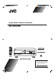
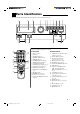
AUDIO/VIDEO CONTROL RECEIVER RX-664VBK CATV/SAT TV POWER VCR AUDIO SOUND CATV CONTROL CD-DISC CONTROL DAP MODE 3D-PHONIC 1 3 2 EFFECT DELAY 4 TEST 5 SEA MODE 6 SEA PRESET MENU 8 7/P 100+ SURROUND 9 MASTER VOLUME RETURN/ENTER – REAR•R + 0 +10 CENTER RX-664V 10 TV VOLUME REAR (L) AUDIO/VIDEO CONTROL RECEIVER SLEEP ONE TOUCH TV/VIDEO OPERATION / TUNER BAND TV D SOUN O ON PH PRESET SEA SOURCE SURROUND ADJUST SETTING + MEMORY ONE TOUCH OPERATION CD TAPE DVD MULTI VCR
Warnings, Cautions and Others CAUTION RISK OF ELECTRIC SHOCK DO NOT OPEN CAUTION To reduce the risk of electrical shocks, fire, etc.: 1. Do not remove screws, covers or cabinet. 2. Do not expose this appliance to rain or moisture. CAUTION: TO REDUCE THE RISK OF ELECTRIC SHOCK. DO NOT REMOVE COVER (OR BACK) NO USER SERVICEABLE PARTS INSIDE. REFER SERVICING TO QUALIFIED SERVICE PERSONNEL.
Once you have found the best DVD MULTI playback, DAP, 3D-PHONIC and Surround mode settings for your listening room, note them in the table below for future reference (even though the receiver memorizes the settings until you change them). For actual setting procedures, see pages 26 to 39.
Table of Contents Parts Identification ...................................................................................... 2 Easy Set Up & Operations ............................................................................ 3 Getting Started........................................................................................... 7 Before Installation ......................................................................................................................................................
Parts Identification Become familiar with the buttons and controls on the receiver before use.
Easy Set Up & Operations If you are already familiar with audio components, following four pages give you enough information to operate your RX-664VBK for enjoyment of surround sound in your listening room.
MASTER VOLUME RX-664V AUDIO/VIDEO CONTROL RECEIVER TUNER/BAND – PRESET SEA SOURCE SURROUND ADJUST SETTING + MEMORY ONE TOUCH OPERATION DVD MULTI STANDBY PHONES SPEAKERS 1 2 POWER _ON —OFF 1. Turn on the power. DIO AU R WE VCR D UN L SONTRO CO PO TV AT C -DIS D TV L C CA TRO N CO V/S T CA ND OU RR SU IC ON 3 2 E OD PM DA 1 6 Y LA CT NU 9 T SE E R AP SE 4 8 E OD R 1 7/P + 100 .
Easy Set Up & Operations For Reproducing DVD MULTI Playback with your DVD player TV To video input Center Speaker Front Speaker Front Speaker RX-664V AUDIO/VIDEO CONTROL RECEIVER Subwoofer Rear Speaker Rear Speaker RX-664VBK FRONT SPEAKERS RIGHT + DVD ANTENNA DVD FRONT CENTER REAR L – LEFT – + VIDEO MONITOR OUT COMPU LINK-3 (SYNCHRO) 1 1 LEFT FM 75 OUT (REC) FM GND RIGHT R 2 IN (PLAY) SUBWOOFER PHONO AM LOOP AM EXT CD AUDIO TAPE TV SOUND OUT (REC) IN (PLAY) – – +
MASTER VOLUME RX-664V AUDIO/VIDEO CONTROL RECEIVER TUNER/BAND – PRESET SEA SOURCE SURROUND ADJUST SETTING + MEMORY ONE TOUCH OPERATION DVD MULTI STANDBY PHONES SPEAKERS 1 2 POWER _ON —OFF 1. Turn on the power. DIO AU R WE VCR D UN L SONTRO CO PO TV T C -DIS D TV L C CA TRO N CO /SA TV CA 2 E OD PM DA 1 T EC F EF 4 9 ET S RE P R R 8 E OD T 7/P + 100 .R AR RE +10 100+ +10 TV ME U OL ER E /VID EP SLE CH OU N E T IO ON ERAT OP TV R/ NE D TUBAN 2.
Getting Started This section explains how to connect stereo components and speakers to the receiver, and how to connect the power supply. Before Installation General • • • Be sure your hands are dry. Turn the power off to all components. Read the manuals supplied with the components you are going to connect. Locations • • Install the receiver in a location that is level and protected from moisture. The temperature around the receiver must be between 23˚ and 95˚ F (–5˚ and 35˚ C).
Connecting the FM and AM Antennas FM Antenna Connections 1 2 3 FM Antenna ANTENNA Extend the FM antenna horizontally. Note: FM 75 FM GND If reception is poor, connect the outside antenna. Before attaching a 75 Ω coaxial cable (the kind with a round wire going to an outside antenna), disconnect the supplied FM wire antenna. Outside FM Antenna Cable 1 GND 2 3 7/16 in. AM LOOP AM EXT 13/16 in. (10 mm) (20 mm) How to strip the 75 Ω coaxial cable and connect it to the FM terminals 1.
Getting Started Connecting the Speakers You can connect the following speakers: • Two sets of front speakers to produce normal stereo sound • One set of rear speakers to enjoy the surround effect • One center speaker to produce more effective surround effect (to make human voices outstanding) • One subwoofer to enhance the bass For each speaker (except for subwoofer), connect one end of the speaker signal cable (not supplied) to the speaker terminal on the rear panel and the other end to the speaker.
Connecting the rear and center speakers Connect the rear speakers to the REAR SPEAKERS terminals and the center speaker to the CENTER SPEAKER terminals. Center speaker CENTER SPEAKER Left rear speaker RIGHT Right rear speaker LEFT REAR SPEAKERS Notes: • When you connect rear speakers, make sure that both left and right speakers are connected; otherwise, no sound will come out of the rear speakers. • You can register the center speaker size after you finish its connection.
Getting Started Connecting Audio/Video Components You can connect the following components to the receiver using cables with RCA pin plugs. Audio Components Video Components • Turntable • TV • CD player • VCR • Cassette deck • DVD player CAUTION: If you connect a sound-enhancing device such as a graphic equalizer between the source components and this receiver, the sound output through this receiver may be distorted.
DVD player connection • When you play back a disc on the DVD player in stereo (or the audio output setting of the DVD player is mixed to two front channels): DVD REAR MONITOR OUT LEFT L DVD player VIDEO DVD CENTER FRONT OUT (REC) RIGHT R IN (PLAY) VCR SUBWOOFER PHONO CD TAPE AUDIO TV SOUND OUT (REC) IN (PLAY) LEFT DVD L To front left/right channel audio output (or to audio mixed output if necessary) R RIGHT OUT (REC) IN (PLAY) To video output • When you play back a disc on the DV
Getting started Connecting the Power Cord Notes: Before plugging the receiver into an AC outlet, make sure that all connections have been made. When the power cord is connected, the STANDBY lamp above the POWER button lights up. Keep the power cord away from the connecting cables for the TV, VCR, and antenna. The power cord may cause noise or screen interference. We recommend that you use a coaxial cable to connect the antenna, since it is well-shielded against interference.
Basic Operations The following operations are commonly used when you play any sound source. Turning the Power On and Off On the front panel: To turn on the power, press POWER. The STANDBY lamp goes off. The name of the current source (or station frequency) appears on the display.
Basic Operations Adjusting the Volume CAUTION: On the front panel: To increase the volume, turn MASTER VOLUME clockwise. To decrease the volume, turn it counterclockwise. MASTER VOLUME – + When you turn MASTER VOLUME rapidly, the volume level also changes rapidly. When you turn MASTER VOLUME slowly, the volume level also changes slowly. From the remote control: Always set the volume to the minimum before starting any source.
Recording a Source You can record any source playing through the receiver to a cassette deck connected to the TAPE jacks and the VCR connected to the VCR jacks at the same time. While recording, you can listen to the selected sound source at whatever sound level you like, without affecting the sound levels of the recording. Listening with Headphones A standard pair of headphones can be connected to the PHONES jack on the front panel.
Basic Settings Some of the following settings are required after connecting and positioning your speakers in your listening room, while others will make operations easier. Adjusting the Front Speaker Output Balance If the sounds you hear from the front right and left speakers are unequal, you can adjust the speaker output balance. On the front panel only: SETTING 1. Press SETTING so that the Control % / fi / @ / # buttons work for adjusting the balance. The lamp above the button lights up. 2.
When the shut-off time comes The receiver turns off automatically. To check or change the time remaining until the shut-off time 1. Press SETTING, if necessary, so that the Control % / fi / @ / # buttons work for setting the Sleep Timer. 2. Press Control % / fi, if necessary, until “SLEEP” appears on the display. 3. Press Control @ / #. The remaining time until the shut-off time appears in minutes. • To change the shut-off time, press Control @ / # repeatedly.
Basic Settings Selecting the Center Speaker Size You can register the information about the center speaker after all connections are completed. If you do this registration first, you do not have to adjust the center speaker mode when you want to activate the surround sound. On the front panel only: 1. Press SETTING so that the Control % / fi / @ / # buttons work for selecting the center speaker size. The lamp above the button lights up. 2.
One Touch Operation This receiver can memorize the optimum sound settings for each playing source. About the One Touch Operation JVC’s One Touch Operation function is used to assign and store different sound settings for each different playing source. By using this function, you do not have to change the settings every time you change the source. The stored settings for the newly selected source are automatically recalled.
Receiving Radio Broadcasts You can browse through all the stations or use the preset function to go immediately to a particular station. Tuning in Stations Manually On the front panel only: Notes: • When you hold down Control @ / # in step 3, the frequency keeps changing until you press Control @ / # again or a station is tuned in. • When a station of sufficient signal strength is tuned in, the TUNED indicator lights up on the display.
5. Repeat steps 1 to 4 until you store all the stations you want. To cancel a stored preset station Storing a new station on a used number erases the previously stored one. To tune in a preset station On the front panel: 1. Press TUNER/BAND so that the Control % / fi / @ / # buttons work for tuner settings. The lamp above the button lights up. TUNER/BAND 2. Press Control % / fi until “–PRESET+” appears on the display. 3. Press Control @ / # to select a preset channel.
Receiving Radio Broadcasts Selecting the FM Reception Mode You can change the FM reception mode while receiving an FM broadcast. Note: On the front panel only: You can store the FM reception mode for each preset station. 1. Press TUNER/BAND so that the Control % / fi / @ / # buttons work for tuner settings. The lamp above the button lights up. TUNER/BAND 2. Press Control % / fi until “FM MODE” appears on the display. 3. Press Control @ / # to select either “FM AUTO” or “FM MONO.
Using the Preset SEA Modes The preset SEA (Sound Effect Amplifier) modes give you control of the way your music sounds. Selecting Your Favorite SEA Mode On the front panel: 1. Press PRESET SEA so that the Control % / fi / @ / # buttons work for preset SEA setting. The lamp above the button lights up. Notes: PRESET SEA • The preset SEA modes cannot be used for recording. • When you turn on the preset SEA mode, the mode with its effect level previously selected is recalled at first. 2.
Using the Preset SEA Modes From the remote control: SOUND CONTROL 1. Press SOUND CONTROL so that 10 keys work for adjusting the sound. 2. Press SEA MODE until the preset SEA mode you want appears on the display. The previously selected mode is recalled (at its previous effect level) and is shown on the display. Each time you press the button, the preset SEA modes change as follows: Music SEA MODE 7/P Movie Sports OFF 3. Press SEA PRESET to select the effect level.
Using the Surround Processor The built-in surround processor provides three groups of Surround Processor modes — JVC 3D-PHONIC mode, DAP (Digital Acoustic Processor) mode, and surround modes (Dolby Surround and JVC Theater Surround). On JVC 3D-PHONIC mode JVC 3D-PHONIC mode gives you such a nearly surround effect as it is reproduced through the Dolby Surround decoder, which is widely used to reproduce sounds with a feeling of movement like those experienced in movie theaters.
Using the Surround Processor Using JVC 3D-PHONIC Modes When using JVC 3D-PHONIC modes, you need only two front speakers to reproduce DOLBY SURROUND . the soundtracks of video software bearing the mark The 3D-PHONIC modes give you very realistic surround effects as if the sound is reproduced through the Dolby Surround decoder. On the front panel: 1. Press SURROUND so that the Control % / fi / @ / # buttons work for selecting the Surround Processor mode. The lamp above the button lights up. SURROUND 2.
6. Press Control @ / # to adjust the effect level. Each time you press the button, the effect level changes as follows: EFFECT 1 EFFECT 2 EFFECT 3 EFFECT 4 EFFECT 5 As the number increases the effect of the selected 3DPHONIC mode becomes stronger. 7. Select and play a sound source which was processed with Dolby Surround and DOLBY SURROUND mark. is labeled with To cancel the 3D-PHONIC mode Select “OFF” in step 2. The 3D-PHONIC indicator goes off from the display. From the remote control: 1.
Using the Surround Processor Using the DAP Modes You can use five DAP modes — “Dance Club, Live Club, Hall, Pavilion, and Headphones.” These modes (except “Headphones”) require the front speakers and the rear speakers, but do not require a center speaker to enlarge the sound field. Among the DAP modes, “Headphones” is very special. It can create the same stereo sound as you listen through the speakers off air while listening to a source using headphones.
5. Press Control % / fi until “– REAR +” appears on the display. Note: Once you have adjusted the DAP modes, the adjustment is memorized for each DAP mode. 6. Press Control @ / # to adjust the rear speaker output level. • Pressing Control @ decreases the output level up to –10 dB. • Pressing Control # increases the output level up to +10 dB. 7. Press Control % / fi until “–EFFECT+” appears on the display. 8. Press Control @ / # to adjust the effect level.
Using the Surround Processor 4. Press EFFECT to select the effect level. Each time you press the button, the effect level changes as follows: EFFECT 1 EFFECT 2 EFFECT 5 EFFECT 4 EFFECT 3 EFFECT 4 To cancel the DAP mode Select “OFF” in step 2. The DAP indicator goes off from the display. 31 RX-664VBK(J)_0119-001B_En.24-50 31 98.1.
With this receiver, you can use two types of the surround modes — Dolby Surround and JVC Theater Surround. Speaker Arrangements for Surround Modes The following illustrations show how to obtain the optimum sound environment for various surround mode settings. Try to find the speaker direction and location to create the optimum sound field. CASE 1 When you have added a center speaker and rear speakers Front speaker TV Center speaker Rear speaker Front speaker In this case: 1.
Using the Surround Processor Preparing for Surround Modes Once you have set the surround modes, you can use the same adjustments every time you want to activate the surround mode you want. The receiver memorizes surround adjustments for each mode. On the front panel: 1. Press SURROUND so that the Control % / fi / @ / # buttons work for selecting the Surround Processor mode. The lamp above the button lights up. SURROUND 2.
5. Press Control @ / # to select the center mode. Each time you press the button, the center modes change as follows: WIDE PHANTOM NORMAL WIDE NORMAL PHANTOM Notes: Select this mode when the center speaker can reproduce the bass better than the front speakers. All signals of the center channel are output through the center speaker. Select this mode when the center speaker cannot reproduce the bass better than the front speakers.
Using the Surround Processor 9. If necessary, adjust the speaker output balance as follows: • To adjust the rear speaker output level, press Control % / fi until “– REAR +” appears on the display, then press Control @ / #. • To adjust the center speaker output level, press Control % / fi until “–CENTER+” appears on the display, then press Control @ / #. Notes: • The sound levels of the left and right rear speakers will be the same.
4. Press TEST to start checking the speaker output balance. “TEST” starts flashing on the display, and a test tone comes out of the speakers in the following order: Left front speaker Center speaker Rear speakers TEST Notes: 6 • No test tone comes out of the rear speakers when you have selected “3CHLOGIC.” • No test tone comes out of the center speaker when you select “PHANTOM” for the center mode. Right front speaker 5.
Using the Surround Processor Using Surround Modes Once you have adjusted the surround mode you can use the same adjustments every time you want to enjoy Surround modes. From the front panel: 1. Press SURROUND so that the Control % / fi buttons work for selecting the Surround Processor mode. The lamp above the button lights up. SURROUND 2. Press Control % / fi to select one of the Surround mode (“PROLOGIC,” “3CHLOGIC” or “THEATER”).
Using the DVD MULTI Playback Mode This receiver provides the DVD MULTI playback mode for reproducing the analog discrete output mode (5.1 CH) of the DVD player. Before playing back a DVD, refer also to the manual supplied with the DVD player. Speaker arrangements for DVD MULTI playback The following illustration show how to obtain the optimum sound environment for the DVD MULTI playback mode. Try to find the speaker direction and location to create the optimum sound field.
Using the DVD MULTI Playback Mode 6. Press Control % / fi until “–REAR L+” appears on the display. 7. Press Control @ / # to adjust the left rear speaker output level. • Pressing Control @ decreases the output level up to –10 dB. • Pressing Control # increases the output level up to +10 dB. 8. Press Control % / fi until “–REAR R+” appears on the display. 9. Press Control @ / # to adjust the right rear speaker output level. • Pressing Control @ decreases the output level up to –10 dB.
COMPU LINK Remote Control System The COMPU LINK remote control system allows you to operate JVC audio components through the remote sensor on the receiver.
AV COMPU LINK Remote Control System The AV COMPU LINK remote control system allows you to operate JVC video components (TV, VCR, and DVD player) through the receiver. To use this remote control system, you need to connect the video components you want to operate, following the procedures below. 1. Connect your VCR, DVD player, and TV as follows, using the cables with the monaural mini-plug (not supplied).
The AV COMPU LINK remote control system allows you to use the five basic functions listed below. Remote Control of the TV, DVD player, and VCR Using This Remote Control See page 44 for details. For the DVD player and the VCR: • Aim the remote control directly at the remote sensor on the each component. For the TV having AV COMPU LINK terminal “RECEIVER/AMP”: • Aim the remote control directly at the remote sensor on the receiver when operating the TV.
Operating Other Components You can operate JVC audio and video components with this receiver’s remote control. To operate these components with the remote control, first select a source with the source buttons on the remote control. Then, operate that source using the remote control.
IMPORTANT: To operate JVC video components using this remote control: • You need to connect JVC video components through the AV COMPU LINK jacks (see page 41). • When operating the VCR and DVD player, aim the remote control directly at the remote sensor on the each component. • When operating the TV having AV COMPU LINK "RECEIVER/AMP,” aim the remote control directly at the remote sensor on the receiver.
Operating Other Manufacturers’ Video Equipment This remote control supplied with the receiver can transmit control signals for other manufacturers’ VCRs, TVs, CATV converters and satellite tuners. By changing the transmittable signals from preset ones to the other manufacturers’, you can operate the other manufacturer’s components using this remote control. When operating the other manufacturers’ components, refer also to the manuals supplied with them.
To change the transmittable signals for operating a CATV converter or satellite tuner 1. Press and hold CATV/SAT (in the POWER section). CATV/SAT TV POWER VCR AUDIO SOUND CATV CONTROL CD-DISC CONTROL 2. Press CATV CONTROL. DAP MODE 3D-PHONIC 3. Enter manufacturer’s code (two digits) using buttons 1–9, and 0. See the list below to find the code.
Operating Other Manufacturers’ Video Equipment To change the transmittable signals for operating another manufacturer’s VCR 1. Press and hold VCR (in the POWER section). CATV/SAT TV POWER VCR AUDIO SOUND CATV CONTROL CD-DISC CONTROL 2. Press VCR. DAP MODE 3D-PHONIC 3. Enter manufacturer’s code (two digits) using buttons 1–9, and 0. See the list below to find the code.
Troubleshooting Use this chart to help you solve daily operational problems. If there is any problem you cannot solve, contact your JVC service center. PROBLEM POSSIBLE CAUSE SOLUTION The display does not light up. The power cord is not plugged in. Plug the power cord into an AC outlet. No sound from speakers. Speaker signal cables are not connected. Check speaker wiring and reconnect if necessary. The SPEAKERS 1 and 2 buttons are not set correctly.
Specifications Output Power At Stereo operation 100 watts per channel, min. RMS, driven into 8 ohms, 40 Hz to 20 kHz with no more than 0.8 % total harmonic distortion. Amplifier Output Power ....................................................... At Surround operation Front channels .......................................................... 100 watts per channel, min. RMS, driven into 8 ohms at 1 kHz, with no more than 0.8% total harmonic distortion. Center channel ........................................
FM tuner (IHF) Tuning Range ............................................................................................................................................. 87.5 MHz to 108.0 MHz Usable Sensitivity ....................................................................................................................................... 10.8 dBf (0.95 µV/75 ohms) 50 dB Quieting Sensitivity .................................. Monaural ...................................................................
QUALITY SERVICE HOW TO LOCATE YOUR JVC SERVICE CENTER TOLL FREE : 1-800-537-5722 Dear customer: In order to receive the most satisfaction from your purchase, read the instruction booklet before operating the unit. In the event that repair is necessary, or for the address nearest your location, please refer to the factory service center list below or within the Continental United States, Call 1-800-537—5722 for your authorized servicer. Remember to retain you Bill of Sale for Warranty Service.
LIMITED WARRANTY AUDIO-2 JVC COMPANY OF AMERICA warrants this product and all parts thereof, except as set forth below ONLY TO THE ORIGINAL PURCHASER AT RETAIL to be FREE FROM DEFECTIVE MATERIAL AND WORKMANSHIP from the date of original retail purchase for the period as shown below. (“The Warranty Period.”) PARTS LABOR 2 YRS 2 YRS THIS LIMITED WARRANTY IS VALID ONLY IN THE FIFTY(50) UNITED STATES, THE DISTRICT OF COLUMBIA AND IN COMMONWEALTH OF PUERTO RICO.
VICTOR COMPANY OF JAPAN, LIMITED V EN RX-664VBK(J)_0119-001B.Cover J 2 98.1.