DIGITAL VIDEO CAMERA GR-DVX4 Please visit our CyberCam Homepage on the World Wide Web and answer our Consumer Survey (in English only): http://www.jvc-victor.co.jp/english/index-e.html CONTENTS PROVIDED ACCESSORIES 4 ABOUT DV 5 GETTING STARTED 6 – 13 RECORDING 14 – 41 Basic Recording ................................ 14 Advanced Features ............................ 20 PLAYBACK 42 – 49 Basic Playback ................................. Advanced Features ............................ Basic Connections .....
EN Dear Customer, Thank you for purchasing this digital video camera. Before use, please read the safety information and precautions contained in the following pages to ensure safe use of this product. Using This Instruction Manual •All major sections and subsections are listed in the Table Of Contents (Z cover page). •Notes appear after most subsections. Be sure to read these as well. •Basic and advanced features/operation are separated for easier reference. It is recommended that you . . . ....
EN NOTES: ● The rating plate (serial number plate) and safety caution are on the bottom and/or the back of the main unit. ● The rating plate (serial number plate) of the AC Power Adapter/Charger is on its bottom. 3 This camcorder is designed to be used with PALtype colour television signals. It cannot be used for playback with a television of a different standard. However, live recording and LCD monitor/ viewfinder playback are possible anywhere.
EN SAFETY PRECAUTIONS PROVIDED ACCESSORIES Do not point the lens or the viewfinder directly into the sun. This can cause eye injuries, as well as lead to the malfunctioning of internal circuitry. There is also a risk of fire or electric shock. CAUTION! The following notes concern possible physical damage to the camcorder and to the user. When carrying, be sure to always attach and use the provided hand strap. Hold the camcorder firmly in your hand, with the strap securely around your wrist.
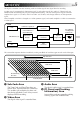
ABOUT DV EN 5 The digital camcorder converts incoming audio and video signals into digital form for recording. A video signal is composed of a luminance signal (Y) and colour signals (R-Y and B-Y). These signals are identified and recorded digitally (Digital Component Recording). The A/D (Analogue to Digital) converter samples the Y signal at 13.5 MHz, and R-Y and B-Y at 6.75 MHz, and changes them to an 8-bit quantum signal.
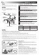
GETTING STARTED EN Power CHARGING THE BATTERY PACK This camcorder’s 2-way power supply system lets you choose the most appropriate source of power. 1 SUPPLY POWER TO CHARGER NOTES: ● No function is available without power supply. ● Use only specified power supply. ● Do not use provided power supply units with other equipment.
EN 7 USING THE BATTERY PACK 1 ATTACH BATTERY1PACK Insert the terminal end of the battery pack into the battery pack mount, then firmly push the end 2 of the battery pack in the direction of the arrow until it locks into place as shown in the illustration. •If the battery pack is attached in the wrong position, a malfunction may occur. 1 To Detach The Battery Pack . . . .... while sliding down BATT. RELEASE, detach it. 2 NOTES: BATT.
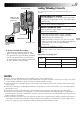
GETTING STARTED (cont.) EN Date/Time Settings A M Date and time will automatically be recorded on tape at all times. It is your choice to display it or not during playback (Z pg. 45). 1 SELECT OPERATION MODE Set the Operation Switch to “ ”. Then, set the Power Switch to “ ” or “5S” while pressing down the Lock Button. Open the LCD monitor fully or pull out the viewfinder fully. Operation Switch •The power lamp comes on and the camcorder is turned on.
EN Cassette holder 9 Loading/Unloading A Cassette The camcorder needs to be powered up to load or eject a cassette. 1 OPEN CASSETTE COVER Make sure the window side is facing out. Slide OPEN/EJECT in the direction of the arrow then swing the cover open until it locks. The holder opens automatically. •Do not touch internal components. 2 INSERT/REMOVE TAPE Insert or remove a tape and press “PUSH HERE” to close the cassette holder.
GETTING STARTED (cont.) EN Recording Mode Setting A Set depending on your preference. M 1 SELECT OPERATION MODE Set the Operation Switch to “ ”. Then, set the Power Switch to “ ” or “5S” while pressing down the Lock Button. Open the LCD monitor fully or pull out the viewfinder fully. Operation Switch •The power lamp comes on and the camcorder is turned on. FF CAME YO 5S RA PLA Lock Button Power lamp 2 ACCESS RECORDING MENU 3 ACCESS MODE MENU Press MENU/SET. The Recording Menu appears.
EN 11 Grip Adjustment START/STOP Button 1 EXPAND LOOP 2 INSERT HAND Power Zoom Lever Separate the Velcro strip. Pass your right hand through the loop and grasp the grip. 3 ADJUST STRAP LENGTH Adjust so that your thumb and fingers can easily operate START/STOP and Power Zoom Lever. Refasten the Velcro strip. NOTE: When carrying the camcorder inside a bag, etc., the grip belt’s metal buckle may damage the camcorder. It is recommended that you place it inside the Velcro strip.
EN GETTING STARTED (cont.) Tripod Mounting 1 ALIGN AND TIGHTEN Align the screw on the tripod with the camera’s mounting socket. Then tighten the screw. CAUTION: When using a tripod, be sure to open and extend its legs fully to stabilise the camcorder. To prevent damage to the unit caused by falling over, do not use a small-sized tripod.
EN To turn on the camcorder, first set the Power Switch to any operation mode except “OFF”, then pull out the viewfinder fully or open the LCD monitor. When setting the Power Switch, press and hold the Lock Button.
RECORDING Basic Recording EN NOTE: You should already have performed the procedures listed below. If not, do so before continuing. ● Power ( Z pg. 6) ● Recording Mode Setting ( Z pg. 10) ● Grip Adjustment ( Z pg. 11) ● Viewfinder Adjustment ( Z pg. 11) 1 LOAD A CASSETTE Slide OPEN/EJECT in the direction of the arrow then swing the cover open until it locks. The holder opens automatically. Insert a tape and press “PUSH HERE” to close the cassette holder.
EN 15 4 STOP RECORDING Press START/STOP again to stop recording. •The camcorder re-enters the Record-Standby mode. NOTES: START/STOP Button Tape remaining time indicator 25 min min (Now calculating) 90 min 89 min 3 min 2 min (Blinking) 1 min (Blinking) 0 min (Blinking) ● The image will not appear simultaneously in the LCD monitor and the viewfinder. No image appears on the LCD monitor when the viewfinder is pulled out. It is not possible to shoot using both LCD monitor and viewfinder.
RECORDING Basic Recording (cont.) EN Shooting While Watching The LCD Monitor 90° 180° Before the following steps, perform step 1 (Z pg. 14). 2 ENTER RECORD–STANDBY MODE Make sure the viewfinder is pushed back in. Set the Operation Switch to “ ” or “ ”. Then, set the Power Switch to “ ” while pressing down the Lock Button. Open the LCD monitor fully. •The lens cover opens, the power lamp lights and the camcorder enters the Record-Standby mode.
EN 17 Journalistic Shooting In some situations different angles of shooting may be required for more dramatic results. 1 OPEN LCD MONITOR 2 TILT LCD MONITOR Make sure the LCD monitor is fully open. Tilt the LCD monitor in the most convenient direction. •The LCD monitor can rotate almost full circle (270°: 90° downward, 180° upward). Interface Shooting A person you shoot can view himself/herself in the LCD monitor, and you can even shoot yourself while viewing your own image in the LCD monitor.
RECORDING Basic Recording (cont.) EN T Zoom in (T: Telephoto) D T 1X W D T 10X W D T D T 20X W 40X W T W Zoom out (W: Wide angle) W Zoom display PURPOSE: To produce the zoom in/out effect, or an instantaneous change in image magnification. OPERATION: Zoom In Slide the Power Zoom Lever towards “T”. Zoom Out Slide the Power Zoom Lever towards “W”. n The further you slide the Power Zoom Lever, the quicker the zoom action.
EN 19 NOTE: Recording From The Middle Of A Tape Time Code During recording, a time code is recorded on the tape. This code is to confirm the location of the recorded scene on the tape during playback. If recording starts from a blank portion, the time code begins counting from “00:00:00” (minute:second:frame). If recording starts from the end of a previously recorded scene, the time code continues from the last time code number. To perform Random Assemble Editing (Z pg. 56 – 61), time code is necessary.
RECORDING Advanced Features Displaying The Date And Time During RECORDING Advanced Features EN A Recording M When the Operation Switch is set to “ ”, you can choose whether to display the date and time during recording or not. You must first set the date and time (“Date/Time Settings”, Z pg. 8). Set “DISPLAY” to “ON” in the Date/ Time Menu. The Date/Time is always displayed when the Operaton Switch is set to “ ”.
EN 21 LCD Monitor/Viewfinder Indications A You can make the LCD monitor/Viewfinder indications appear/disappear. M 1 SELECT OPERATION MODE Set the Operation Switch to “ ”. Then, set the Power Switch to “ ” or “5S” while pressing down the Lock Button. Operation Switch 2 ACCESS RECORDING MENU 3 ACCESS MODE MENU Press MENU/SET. The Recording Menu appears. MENU/SET Dial FF CAME YO 5S RA PLA Lock Button Power lamp Power Switch Display FOCUS EXPOSURE W. BALANCE FADER / WIPE P.
RECORDING Advanced Features (cont.) EN Scene (5-second recording) Operation Switch A Record a vacation or an important event in 5-second clips to keep the action moving. M START/STOP Button 1 SELECT OPERATION MODE Set the Operation Switch to “ ” or “ ”, then set the Power Switch to “5S” while pressing down the Lock Button. Pull out the viewfinder fully or open the LCD monitor fully. Power Switch PLAY OFF Power lamp MERA 5S CA Lock Button SNAPSHOT Button Press START/STOP.
EN 23 Self-Timer Operation Switch MENU/SET Dial START/STOP Button Once the camcorder is set, the camcorder operator can become part of the scene in a more natural way, adding the final touch to a memorable picture. 1 SELECT OPERATION MODE Set the Operation Switch to “ ”. Then, set the Power Switch to “ ” (or “5S”) while pressing down the Lock Button. Pull out the viewfinder fully or open the LCD monitor fully. FF CAME YO 5S RA PLA Power lamp Lock Button Power Switch Display FOCUS EXPOSURE W.
RECORDING Advanced Features (cont.) EN A Snapshot M Use your camcorder like a regular camera and take a snapshot, or several of them in succession. SNAPSHOT MODE SELECTION Operation Switch 1 SELECT OPERATION MODE FF CAME YO 5S RA PLA Power lamp Lock Button SNAPSHOT Button Display Power Switch FULL Set the Operation Switch to “ ” or “ ”. Then, set the Power Switch to “ ” while pressing down the Lock Button. Pull out the viewfinder fully or open the LCD monitor fully.
EN 25 Multi Screen Mode The screen is divided into 9 quadrangles, with the scene you are aiming at appearing in each one. This 9-quadrangle image can be recorded onto a tape. 1 SELECT OPERATION MODE Set the Operation Switch to “ ” or “ ”. Then, set the Power Switch to “ ” or “5S” while pressing down the Lock Button. 2 ACTIVATE MULTI SCREEN Press MULTI SCREEN. [Power Switch: “ ”] If you press MULTI SCREEN during recording. . . ....
RECORDING Advanced Features (cont.) EN MENU/SET Dial Operation Switch FF CAME YO 5S RA PLA Power lamp Lock Button Power Switch SNAPSHOT Button Display FOCUS EXPOSURE W. BALANCE FADER / WIPE P. AE / EFFECT FLASH ADJ. 4 TO MODE MENU END AUTO AUTO AUTO OFF Recording Menu Snapshot Flash (Auto Flash) In Full Auto or Manual mode, when “FLASH” is set to “AUTO” or “AUTO ” in the Mode Menu, the flash automatically fires if it’s dark ( appears) when a snapshot is taken in Record-Standby.
EN 27 Flash Brightness Adjustment A When a snapshot (Z pg. 24) is taken in the dark the camcorder fires the flash (Z pg. 26) and adjusts the brightness automatically. You can also adjust the flash brightness manually. When you find that the snapshots you took look too bright or too dark, adjust it manually. M 1 SELECT OPERATION MODE Operation Switch Set the Operation Switch to “ ”. Then, set the Power Switch to “ ” or “5S” while pressing down the Lock Button.
RECORDING Advanced Features (cont.) EN Operation Switch MENU/SET Dial Using Menu For Detailed Adjustment This camcorder is equipped with an easy-to-use, on-screen menu system that simplifies many of the more detailed camcorder settings. 1 SELECT OPERATION MODE FF CAME YO 5S RA PLA Power lamp Lock Button Display 4 FOCUS EXPOSURE W. BALANCE FADER / WIPE P. AE / EFFECT FLASH ADJ. TO MODE MENU END Power Switch MANUAL AUTO AUTO OFF Recording Menu Set the Operation Switch to “ ”.
EN 29 Recording Menu Explanations FOCUS Refer to “Focusing” (Z pg. 36, 37). EXPOSURE Refer to “Exposure Control” and “Iris Lock” (Z pg. 38, 39). W.BALANCE Refer to “White Balance Adjustment” and “Manual White Balance Operation” (Z pg. 40, 41). FADER/WIPE Refer to “Fade/Wipe Effects” (Z pg. 31 – 33). P.AE/EFFECT Refer to “Programme AE With Special Effects” (Z pg. 34, 35). FLASH ADJ. Refer to “Flash Brightness Adjustment” (Z pg. 27). TO MODE MENU Refer to “Mode Menu Explanations” below.
EN Date/Time Menu Explanations INDICATION ON SCREEN DISPLAY DATE/TIME ON RECORDING Advanced Features (cont.) Makes all the indications appear in the camcorder (Z pg. 21). OFF Keeps all the indications (except the tape running indicator, warnings, etc.) from appearing in the camcorder (Z pg. 21). OFF Keeps the camcorder’s display from appearing on the connected TV screen. ON Makes the camcorder’s display appear on screen when the camcorder is connected to a TV.
EN A 31 Fade/Wipe Effects M IMPORTANT: If certain modes of Programme AE with special effects ( Z pg. 34) are activated, some Fade/Wipe Effects cannot be used. If you select a Fade/Wipe Effect that is unusable in the current situation, the indication blinks. START/STOP Button These effects let you make pro-style scene transitions. Use these to spice up the transition from one scene to the next. You can also vary transitions from scene to scene.
RECORDING Advanced Features (cont.) EN PICTURE WIPE OR DISSOLVE SELECTION ( , , , , , and ) START/STOP Button Combine the Picture Wipe and Dissolve functions for a professional transition effect. There are 6 Picture Wipe effects and 1 Dissolve effect. The Picture Wipe or Dissolve works when recording is started. Before the following steps, perform steps 1 through 4 on pg. 31. 5 STORE SCENE IN MEMORY ,,, ,,,, ,,,, ,,,, ,,,, Previous scene end [Ex.: Within 5 minutes . . .
EN 33 Fader And Wipe Menu Menu FADER — WHITE FADER — BLACK FADER — MOSAIC Effect Fade in or out with a white screen. Fade in or out with a black screen. Fade in or out with a full-screen mosaic effect. FADER — B.W Fade in to a colour screen from a black and white screen, or fade out from colour to black and white. WIPE — CORNER Wipe in on a black screen from the upper right to the lower left corner, or wipe out from lower left to upper right, leaving a black screen.
RECORDING Advanced Features (cont.) EN Programme AE With Special Effects A M IMPORTANT: If certain Fades or Wipes ( Z pg. 33) are activated, some modes of Programme AE with special effects cannot be used. If you select a mode that is unusable in the current situation, the mode's symbol blinks. Operation Switch You can choose any one of the effects from the P.AE/ EFFECT Menu.
SHUTTER (Variable Shutter Speed) ,,,, ,,,, ,,,, ,,,, 1/50–The shutter speed is fixed at 1/50th of a second. Black bands that usually appear when shooting a TV screen become narrower. 1/100–The shutter speed is fixed at 1/100th of a second. The flickering that occurs when shooting under a fluorescent light or mercury-vapour lamp is reduced. 1/250, 1/500–These settings allow fast-moving images to be captured one frame at a time, for vivid, stable slow-motion playback.
RECORDING Advanced Features (cont.) EN Focus detection zone Focusing AUTO FOCUS The camcorder’s Full Range AF system offers continuous shooting ability from close-up (as close as approx. 5 cm to the subject) to infinity. However, correct focus may not be obtainable in the situations listed below (in these cases use manual focusing): •When two subjects overlap in the same scene. •When illumination is low.
EN 37 MANUAL FOCUS A NOTE: M You should already have made the necessary viewfinder adjustments ( Z pg. 11). If you have not, do so before continuing. 1 SELECT OPERATION MODE Operation Switch Set the Operation Switch to “ ”. Then, set the Power Switch to “ ” or “5S” while pressing down the Lock Button. Pull out the viewfinder fully or open the LCD monitor fully. FF CAME YO 5S RA PLA Lock Button Power lamp 2 ACCESS RECORDING MENU 3 ACCESS “FOCUS” Press MENU/SET. The Recording Menu appears.
RECORDING Advanced Features (cont.) EN Exposure Control A This feature automatically adjusts the iris for the best available picture quality, but you can override and make the adjustment manually. M 1 SELECT OPERATION MODE Set the Operation Switch to “ ”. Then, set the Power Switch to “ ” or “5S” while pressing down the Lock Button. Pull out the viewfinder fully or open the LCD monitor fully. Operation Switch BACK LIGHT Button 2 ACCESS RECORDING MENU 3 ACCESS “EXPOSURE” Press MENU/SET.
EN Iris Lock Operation Switch A 39 Use this function when shooting a moving subject, when zooming, when the subject changes its distance (thus its size in the LCD monitor or the viewfinder), or when you want to lock the brightness level. When the subject is close, keep the iris locked. Even when the subject moves away from you, the image will not darken or brighten. M 1 SELECT OPERATION MODE Set the Operation Switch to “ ”.
RECORDING Advanced Features (cont.) EN White Balance Adjustment A A term that refers to the correctness of colour reproduction under various lighting. If the white balance is correct, all other colours will be accurately reproduced. The white balance is usually adjusted automatically. However, the more advanced camcorder operator would prefer to control this function manually and achieve a more professional colour/tint reproduction.
EN 41 Manual White Balance Operation White paper If the camera is operating in Manual mode “ ”, perform Manual White Balance when shooting under various types of lighting. MODE 1 SELECT OPERATION Z Follow steps 1 through 5 of the white balance adjustment ( pg. 40), and select “ MAN.”. 2 SET MANUAL WHITE BALANCE Hold a sheet of plain white paper in front of the subject. Adjust zoom or position yourself so that the white paper fills the screen.
PLAYBACK Basic Playback EN 1 LOAD A CASSETTE Slide OPEN/EJECT in the direction of the arrow, then swing the cassette cover open until it locks. The holder opens automatically. Insert a tape and press “PUSH HERE” to close the cassette holder. OPEN/EJECT Switch 2 SELECT OPERATION MODE Set the Power Switch to “ ” while pressing down the Lock Button. The power lamp lights. Lock Button 3 PLAY BACK 4 STOP PLAYBACK Press 4/6. The playback picture appears.
EN Play/Pause (4/6) Button Fast-Forward (3) Button Rewind (2) Button Stop (5) Button 43 FEATURE: Still Playback PURPOSE: To pause during playback. OPERATION: 1) Press 4/6 during playback. 2) To resume normal playback, press 4/6 again. NOTES: ● If still playback continues for more than about 3 minutes, the camcorder’s Stop mode is automatically engaged. After 5 minutes in the Stop mode, the camcorder’s power is automatically turned off.
PLAYBACK Advanced Features EN Playback Menu The Playback Menu allows you to set the following functions: Playback Sound (32 kHz, 48 kHz), Synchro Comp, Indication, Display and Time Code. The following procedure applies to all except Synchro Comp ( Z pg. 60, 61). 1 SELECT OPERATION MODE Set the Power Switch to “ ” while pressing down the Lock Button. Pull out the viewfinder fully or open the LCD monitor fully. Lock Button Press MENU/SET. The Playback Menu appears.
EN 45 Playback Sound During playback, the camcorder detects the sound mode in which the recording was made, and plays the sound back. Select the type of sound to accompany your playback picture. (32 kHz is preset to “SOUND 1” and 48 kHz is preset to “FULL SOUND”.
PLAYBACK Basic Connections EN These are some basic types of connections. When making the connections, refer also to your VCR and TV instruction manuals. A. Connection to a TV or VCR equipped with a SCART connector compatible only with regular video signal Use the provided Audio/Video (A/V) cable [mini-plug to RCA plug]. * When connecting the cables, open this cover.
EN 47 C. Connection to a TV or VCR equipped with an S-VIDEO IN and/or A/V input (RCA type) connectors Use the provided Docking Station, Audio/Video (A/V) cable [RCA plug to RCA plug] and S-Video cable. To TV or VCR ( ) Yellow to VIDEO IN p When the S-Video [ Yellow to VIDEO OUT cable is not used.
PLAYBACK Advanced Connections EN PC with DV connectorequipped capture board PC Connection To A Personal Computer This camcorder can transfer still images to a personal computer by using the provided software when connected as shown in the illustration. It is also possible to transfer still images to a personal computer with a DV connectorequipped capture board installed. 1 CONFIRM POWER-OFF STATUS 2 CONNECT TO PC Make sure the camcorder and PC are turned off.
EN 49 Connection To A Video Unit Equipped With A DV Connector Power Switch Power lamp Connection to the Digital Printer GV-DT3 (optional) allows you to print out the images or to transfer the captured image from the Digital Printer to a personal computer. It is also possible to copy recorded scenes from the camcorder onto another video unit equipped with a DV connector. This function is called Digital Dubbing (Z pg. 51), which offers virtually no image or sound deterioration.
TAPE DUBBING EN Play/Pause (4/6) Button Tape Dubbing 1 CONNECT EQUIPMENT Following the illustration at left, connect the camcorder and the VCR. Also refer to pg. 46 and 47. 2 PREPARE FOR DUBBING Set the camcorder’s Power Switch to “ ”, turn on the VCR’s power, and insert the appropriate cassettes in the camcorder and the VCR. 3 SELECT VCR MODE 4 FIND EDIT-IN POINT Engage the VCR’s AUX and Record-Pause modes. Engage the camcorder’s Play mode to find a spot just before the edit-in point.
EN 51 Digital Dubbing It is also possible to copy recorded scenes from the camcorder onto other video unit equipped with a DV connector. Since a digital signal is sent, there is little if any image or sound deterioration. Power Switch PLA FF CAME YO 1 CONFIRM POWER-OFF STATUS 2 MAKE CONNECTIONS 5S RA Make sure the camcorder’s power is off. Lock Button Open the connector cover.
USING THE REMOTE CONTROL UNIT EN The Full-Function Remote Control Unit can operate this camcorder from a distance as well as the basic operations (Playback, Stop, Pause, Fast-Forward and Rewind) of your VCR. This remote control unit makes additional playback functions possible. Installing The Battery 2 1 The remote control uses one lithium battery (CR2025). 3 1 PULL OUT BATTERY HOLDER Pull out the battery holder while pressing the knob as shown.
EN 1 0 ! 2 4 3 53 T W @ # $ % ^ & * ( 5 6 7 8 9 ) RM-V713U (provided) Functions Buttons 1 PAUSE IN Connector 2 Zoom (T/W) Buttons With the camcorder’s Power Switch set to the camera position (“ ” or “5S”) . — Zoom in/out (Z pg. 18) 3 DISPLAY Button — 4 SHIFT Button — 5 SLOW Rewind/Forward Buttons — — Left/Right Buttons 6 FADE/WIPE Button — 7 REW Button — 8 EFFECT Button — 9 EFFECT ON/OFF Button — With the camcorder’s Power ”. Switch set to “ Z pg. 57 Zoom in/out (Z pg.
USING THE REMOTE CONTROL UNIT (cont.) EN FEATURE: Slow-Motion Playback PURPOSE: To allow slow-speed search in either direction. Power Switch OPERATION: 1) To change from normal to Slow-Motion Playback, press PAUSE (6) at the point where you want to start playback in slow motion. 2) Press SLOW (9 or 0). After playing back for approx. 1 minute in Slow Rewind or approx. 2 minutes in Slow Forward, normal playback resumes. n To stop Slow-Motion Playback in progess, press PLAY (4).
EN 55 FEATURE: Playback Special Effects PURPOSE: To allow you to add creative effects to the playback image. You can use any one of the 5 effects. Power Switch OPERATION: 1) To start playback, press PLAY (4). 2) Point the remote control at the camcorder's remote sensor and press EFFECT. The PLAYBACK EFFECT Select Menu appears. 3) Move the highlight bar to the desired effect by pressing EFFECT. The selected function is activated and after 2 seconds the menu disappears.
USING THE REMOTE CONTROL UNIT (cont.) EN Random Assemble Editing [R.A.Edit] Create edited videos easily using your camcorder as the source player. You can select up to 8 “cuts” for automatic editing, in any order you like. R.A.Edit is more easily performed when the RM-V713U MBR (Multi-Brand Remote, Z pg. 52) is set to operate with your brand of VCR (see VCR CODE LIST), but can also be performed by operating the VCR manually.
EN 57 MAKE CONNECTIONS Also refer to pg. 46, 47 and 49. TO . . . 1 CONNECT JVC VCR EQUIPPED WITH REMOTE PAUSE TERMINAL Connect the editing cable to the Remote PAUSE terminal. To EDIT Yellow to VIDEO OUT* To S-VIDEO OUT Red to AUDIO R OUT JVC VCR NOT EQUIPPED WITH REMOTE PAUSE TERMINAL BUT EQUIPPED WITH R.A.EDIT CONNECTOR Connect the editing cable to the R.A.EDIT connector.
USING THE REMOTE CONTROL UNIT (cont.) EN SELECT SCENES (cont.) Programme Power Switch IN OUT MODE 1 –– –– : –– ~ 2 3 ~ 4 ~ 5 ~ 6 ~ 7 ~ 8 ~ 4 TIME CODE –– : –– 00 : 00 TOTAL PLA FF CAME YO Random Assemble Editing Menu 6 SET EDIT-IN POINT At the beginning of the scene, press EDIT IN/OUT on the remote control. The Edit-In position appears on the Random Assemble Editing Menu. 7 SET EDIT-OUT POINT At the end of the scene, press EDIT IN/OUT.
EN 59 AUTOMATIC EDITING TO VCR 11 PREPARE SOURCE TAPE Rewind the tape in the camcorder to the beginning of the scene you want to edit and press PAUSE (6). 12 ENGAGE VCR'S RECORD-PAUSE MODE Point the remote control towards the VCR’s remote sensor and press VCR REC STBY (q6), or manually engage the VCR’s Record-Pause mode. START/STOP Button 13 START EDITING Press START/STOP on the camcorder. Editing proceeds as programmed, right through to the end of the last registered scene.
USING THE REMOTE CONTROL UNIT (cont.) EN For More Accurate Editing Some VCRs make the transition from Record-Standby to Record mode faster than others. Even if you begin editing for the camcorder and the VCR at exactly the same time, you may lose scenes you wanted, or find that you have recorded scenes you did not want. For a cleanly edited tape, confirm and adjust the timing of the camcorder against your VCR.
EN 61 ADJUSTMENT OF VCR’S AGAINST CAMCORDER TIMING 4 ACCESS PLAYBACK MENU Point the remote control at the camcorder’s remote sensor and press R.A.EDIT ON/OFF to make the Random Assemble Editing menu disappear, then press MENU/SET. The Playback Menu appears. 5 SELECT FUNCTION Move the highlight bar to “SYNCHRO” by rotating MENU/SET, then press it. The value for “SYNCHRO” is highlighted. PLA FF CAME YO 5S RA MENU/SET Dial Power Switch Press MENU/SET twice. FULL SOUND SOUND1 0.
USING THE REMOTE CONTROL UNIT (cont.) EN Audio Dubbing The audio track can be customized only when recorded on the 32 kHz mode (Z pg. 30). NOTES: ● Audio Dubbing is not possible on a tape recorded at 48 kHz, on a tape recorded in the LP mode or on a blank portion of a tape. ● To perform Audio Dubbing while watching in the television, make connections (Z pg. 46).
TROUBLESHOOTING EN 63 If, after following the steps in the chart below, the problem still exists, please consult your nearest JVC dealer. The camcorder is a microcomputer-controlled device. External noise and interference (from a TV, a radio, etc.) might prevent it from functioning properly. In such cases, first disconnect its power supply unit (battery pack, AC Power Adapter/Battery Charger, etc.) and wait a few minutes; and then re-connect it and proceed as usual from the beginning.
EN SYMPTOM TROUBLESHOOTING (cont.) POSSIBLE CAUSES CORRECTIVE ACTION 9. Snapshot mode cannot be used. 9. • The Squeeze mode is selected. 9. • Disengage the Squeeze mode (Z pg. 29). 10. Although Snapshot is attempted, flash does not take place. 10. • The subject is too bright with the flash set to “AUTO” or “AUTO ”. • If blinks, the flash is being charged. • Multi-Analyser 4 or MultiAnalyser 9 is selected. • The camcorder is in the Record mode. 10. • Set “FLASH” to “ON” in the Mode Menu (Z pg.
EN 65 SYMPTOM POSSIBLE CAUSES CORRECTIVE ACTION 16. Programme AE with special effects and Fade/Wipe Effects do not work. 16. • The Operation Switch is set to “ ” and/or the Power Switch is set to “5S”. 16. • Set the Operation Switch to “ ” and/or set the Power Switch to “ ”. 17. The Black & White Fader does not work. 17. • The Sepia or Monotone mode is activated. 17. • Turn off Sepia and Monotone (Z pg. 34). 18. The Dissolve function does not work. 18.
EN TROUBLESHOOTING (cont.) SYMPTOM POSSIBLE CAUSES CORRECTIVE ACTION 22. The Video Echo mode does not work. 22. • The Picture Wipe or Dissolve functions are in use. • The Squeeze mode is selected in the Mode Menu. • A Fade-In or Fade-Out is in progress (White Fader, Black Fader or Black & White Fader). • Dissolve during 5-second mode recording is in use. 22. • Make sure the Squeeze mode is set to “OFF” (Z pg. 28, 29).
EN SYMPTOM POSSIBLE CAUSES 67 CORRECTIVE ACTION 31. The rear of the LCD monitor is hot. 31. • The light used to illuminate the LCD monitor causes it to become hot. 31. • Close the LCD monitor to turn it off or set the Power Switch to “OFF”, and let the unit cool down. 32. The indicators and the image colour on the LCD monitor are not clear. 32. • This may occur when the surface or the edge of the LCD monitor is pressed. 32. 33. The LCD monitor or viewfinder indications blink. 33.
TROUBLESHOOTING (cont.) EN SYMPTOM POSSIBLE CAUSES CORRECTIVE ACTION 39. Images on the LCD monitor are jittery. 39. • The speaker volume is too great. 39. • Turn the speaker volume down (Z pg. 42). 40. The LCD monitor, the viewfinder and the lens have become dirty (ex. fingerprints). 40. ———— 40. • Wipe them gently with soft cloth. Wiping strongly can cause damage. 41. An unusual mark appears. 41. ———— 41.
USER MAINTENANCE 69 After Use Cassette holder PUSH HERE Remove. EN OPEN/EJECT Switch 1 2 Turn off the camcorder. 3 4 Press “PUSH HERE” to close the cassette cover. Slide down OPEN/EJECT in the direction of the arrow, then swing the cover open until it locks. The cassette holder opens automatically. Remove the cassette. Slide down BATT. RELEASE and remove the battery pack. Cleaning The Camcorder 1 CLEAN EXTERIOR Wipe gently with a soft cloth.
INDEX Controls, Connectors And Indicators EN 12 3 e r t y u i 4 5 6 7 p q o Q E ( * W 89 ! @ 0 PLAY O CAMERA FF # w % 5S 70 $ ^ R & T )
EN 71 Controls Connectors 1 Snapshot Mode Button The connectors * to ) are located beneath the cover. * Digital Video Connector [DV OUT] (i.link*) ......................... Z pg. 49, 51 * i.Link refers to the IEEE1394-1995 industry specification and extensions thereof. The logo is used for products compliant with the i.Link standard. ( •Audio/Video Output Connector [AV OUT] ........................................ Z pg. 46 • Headphones Connector [ ] ............ Z pg.
INDEX Indications EN LCD Monitor/Viewfinder Indications During Recording 1* y D T a 100X W No. 1* 2 3 4 5 6* 7* 8* 9 0 ! @ # $ % ^* & * ( ) q w e r t y b t r e w q ) ( * 2 3 4 5 6* 7* 8* MANUAL A WH 1/250 LP 35 min PS REC 9 444 6w ! PAUSE 0 0 L PHOTO E01 TAPE ! 160 X SET DATE / TIME ! 5S MODE SOUND 32kHz 25 . 12 . 99 16 : 40 TC 12 : 34 : 24 – – – – –6 – – – – – BRIGHT # % 0 @ $ ^* & Function (Z pg. 13) Displays the operation mode position.
EN 73 LCD Monitor/Viewfinder Indications During Playback No. 1 2 3 32kHz SOUND1 LP 4 PS WIDE 4 3 2 6 64 16 e 6e 6e HIGH SPEED 5 : : : : : : : : (Z pg. 45) Playback Fast-Forward/Shuttle search Rewind/Shuttle search Pause Forward slow-motion Reverse slow-motion Audio Dubbing Audio Dubbing Pause 4 Displays the date/time. (Z pg. 45) 5 BRIGHT: Displays the brightness of the LCD 25 . 12 . 99 16 : 40 TC 01 : 28 : 15 VOLUME – – – – –6– – – – – 6 Function 1 Displays the sound mode.
INDEX Docking Station EN 1 JLIP (Joint Level Interface Protocol) Connector 4 5 6 1 2 3 7 8 9 0 ! Connect to a JLIP-compatible camcorder or VCR to control it from the computer using the provided Software. NOTE: Make sure that the camcorder is turned on while connecting the camcorder to a PC using the Docking Station’s JLIP connector. If the camcorder is turned off (because the Power Switch is set to “OFF” or due to Auto Shut Off* etc.
INDEX Terms A AC Power Adapter/Charger ..................... Z pg. 6, 7 Animation ................................................ Z pg. 30 Audio Dubbing ........................................ Z pg. 62 Auto Focus ............................................... Z pg. 36 Auto Shut off ...................................... Z pg. 15, 42 B Back Light Compensation ......................... Z pg. 38 Battery Low .............................................. Z pg. 73 Battery Pack .............................
CAUTIONS EN Battery Packs The supplied battery pack is a lithium-ion battery. Before using the supplied battery pack or an optional battery Terminals pack, be sure to read the following cautions: 1. To avoid hazard . . . .... do not burn. .... do not short-circuit the terminals. .... do not modify or disassemble. .... do not expose the battery to temperatures exceeding 60°C (140°F), as this may cause the battery to overheat, explode or catch fire. .... use only specified chargers. 2.
EN .... in places subject to extremely high (over 40°C or 104°F) or extremely low (under 0°C or 32°F) temperatures. 3. DO NOT leave the unit . . . .... in places of over 50°C (122°F). .... in places where humidity is extremely low (below 35%) or extremely high (above 80%). .... in direct sunlight. .... in a closed car in summer. .... near a heater. 4. To protect the unit, DO NOT . . . .... allow it to become wet. .... drop the unit or strike it against hard objects. ....
SPECIFICATIONS EN Camcorder General Power supply : DC 6.3 V DC 7.2 V Power consumption LCD monitor off, viewfinder on LCD monitor on, viewfinder off Format Signal format Video signal recording format Cassette Tape Speed : : : : : : : Maximum recording time : Pickup Lens Filter diameter LCD monitor Viewfinder Speaker Operating temperature Operating humidity Storage temperature Dimensions : : : : : : : : : : Weight : (Using the AC Power Adapter/Charger) (Using battery pack) Approx. 4.
EN 79 Docking Station General Dimensions Weight : 115 mm (W) x 31 mm (H) x 55 mm (D) : Approx. 90 g Connectors S-Video Video Audio JLIP Editing PC External microphone input : Y: 1 Vp-p, 75 Ω, analogue output C: 0.29 Vp-p, 75 Ω, analogue output : 1 Vp-p, 75 Ω, analogue output : –8 dBs, 1 kΩ, analogue output : ø3.5 mm, 4-pole, mini-head jack (compatible with RC-5325 plug) : ø3.5 mm diameter, 2-pole : ø2.5 mm, 3-pole : –68 dBs, high impedance unbalanced with ø3.5 mm (stereo) E & O.E.
GR-DVX4 VICTOR COMPANY OF JAPAN, LIMITED COPYRIGHT© 1999 VICTOR COMPANY OF JAPAN, LTD.