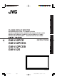
ENGLISH DEUTSCH FRANÇAIS BEDIENUNGSANLEITUNG : PLASMABILDSCHIRM MANUEL D'INSTRUCTIONS : MONITEUR DE VISUALISATION PLASMA MANUALE D'ISTRUZIONI : MONITOR CON SCHERMO AL PLASMA MANUAL DE INSTRUCCIONES : MONITOR DISPLAY DE PLASMA INSTRUCTIONS ESPAÑOL GM-V42PCE GM-V42PCEG GM-V42PCEB GM-V42S MENU INPUT POWER LCT1390-001B Cover. GM-V42PCE Page 3 ITALIANO PLASMA DISPLAY MONITOR 6/18/03, 10:03 PM Adobe PageMaker 6.
ENGLISH INSTRUCTIONS Thank you for purchasing this JVC Monitor. Before using the monitor, read this manual carefully so that you know how to use the Monitor correctly. Refer to this manual whenever questions or problems about operation arise. Be sure to read and observe the safety precautions. Keep this manual where the user can see it easily. * Installation and removal require special expertise. Consult your product dealer for details.
Safety Precautions EUROPE EMC STANDARD NOTICE ■ GM-V42PCE/GM-V42PCEG/GM-V42S Warning: This is a class A product. In a domestic environment this product may cause radio interference in which case the user may be required to take adequate measure. IMPORTANT INFORMATION WARNING: TO REDUCE THE RISK OF FIRE AND ELECTRIC SHOCK, DO NOT EXPOSE THIS APPARATUS TO RAIN, MOISTURE, DRIPPING OR SPLASHING AND THAT NO OBJECTS FILLED WITH LIQUIDS, SUCH AS VASES, SHALL BE PLACED ON THE APPARATUS.
– Power-supply cords should be routed so that they are not likely to be walked on or pinched by items placed upon or against them. Pay particular attention to cords at doors, plugs, receptacles, and the point where they exit from the product. – For added protection of this product during a lightning storm, or when it is left unattended and unused for long periods of time, unplug it from the wall outlet and disconnect the cable system.
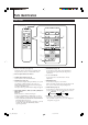
Parts Identification Remote Control 1 2 RM–C579 REMOTE CONTROL UNIT RM–C579 REMOTE CONTROL UNIT OFF POWER DISPLAY ON 3 ASPECT INPUT SELECT COMPO. A /(RGB B) DISPLAY B RGB A VOLUME 5 ON ASPECT 9 INPUT SELECT COMPO. A /(RGB B) VIDEO B MUTING MENU/EXIT POWER 4 VIDEO MUTING OFF RGB A VOLUME 6 p 7 8 MENU/EXIT 1 Remote control cable jack (page 11) Connect the remote control cable (not supplied) when using this remote control as a wired remote control.
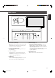
ENGLISH Monitor: Front View 1 2 MENU INPUT MENU INPUT Bottom View 3 1 Remote sensor/power lamp Point the front end of the wireless remote control toward here. When the Monitor is turned on, the power lamp glows green. It glows orange in standby mode. 2 Self-diagnostic lamps (page 39) These lamps light/flash if something abnormal occurs with the Monitor. 3 2 / 3 / 5 / ∞ buttons Use these buttons to select menu items and to make adjustments.
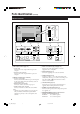
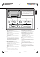
Parts Identification (Continued) Monitor: Rear Views OPTION 6 7 L ( ( R 9 SPEAKER OUT 9 EXTERNAL 8 INTERNAL 1 2 3 4 OUT AUDIO L MAKE IN RS-232C REMOTE RGB A WIRED R AUDIO 1 RGB A input terminals (page 11) • D-sub, 15 pin Connect to the video output terminal of a personal computer. • AUDIO IN (stereo mini jack) Connect to the audio output terminal of a personal computer.
9 VIDEO AUDIO L/MONO R p IN OUT VIDEO A R q VIDEO AUDIO L/MONO ENGLISH Note: * GM-V42PCE, GM-V42PCEG and GM-V42PCEB do not have the following input terminals— VIDEO A, VIDEO B, and COMPONENT/RGB B. To input video, S-video, and component signals, you need to install video input unit (IF-C42P1G), which is separately purchased.
Preparations Checking the Accessories The following accessories are included with the Monitor. Check for them. If any item is missing, please contact the dealer where you purchased the Monitor. • • • • • Remote control (RM-C579) x 1 Power cord x 2 (3 for Australia) (Use the one matching the wall outlet.) Batteries (AA/R6P) x 2 BNC-RCA convension plug x 3 (For Australia) Ferrite core x 1 (Except for GM-V42PCEB) Installing the Batteries Put the batteries in the remote control as follows.
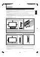
Installation • When mounting the Monitor vertically, consult your dealer. (See also page 13.) • When installing the Monitor, be sure to use a dedicated Stand Unit, Wall Mounting Unit, or Monitor Hanger Unit, depending on a particular case. Ask your dealer for installation. • When installing the Monitor, refer also to the user manual for each option to use. Do not tilt the Monitor rightward, leftward, or backward.
Connections Precautions • • • • • Before making connections, turn off all the equipment. Plugs should be firmly inserted; poor connection could cause noise. To unplug a cord, be sure to grasp its plug and pull it out. Connect the power cord after having finished all other connections. Refer also to the user manual of each piece of equipment. Available Signals Video signals The following signals can be input to this Monitor: • VIDEO A and VIDEO B terminals accept — PAL, PAL60, NTSC, NTSC4.
Typical connections ENGLISH Connection Diagrams ❊ For connection, see page 13. Personal computer Personal computer (used as the playback source) (used to control the Monitor) Remote control (supplied) Amplifier, etc. MENU/EXIT MUTING VOLUME B RGB A VIDEO A /(RGB B) INPUT SELECT COMPO.
Connections (Continued) These terminals are not available for GM-V42PCE, GM-V42PCEG and GM-V42PCEB. To use them, you need to install video input unit (IF-C42P1G), which is separately purchased. AV connections VCR 1 VCR 2 DVD player, etc.
Connecting an external control unit ENGLISH When connecting the external control unit to the MAKE terminal, you can operate the following functions through the MAKE terminal; • Turn on or off the Monitor. Preparation: The POWER switch on the rear must be set to “| (on)” (so that the Monitor is in standby mode). • Select the input. Preparation: “REMOTE SWITCH” should be set correctly to select your desired input (see page 27). Notes: • There is no remote control on/off switch.
Basic Operations Daily Operations 1 Rear View Turn on the main power. Set POWER on the back of the Monitor to “| (on)”. The POWER lamp on the upper left of the front panel glows orange. 2 Turn on the power. Press POWER ON on the remote control to turn the power on. The POWER lamp changes to glow green. button on the front panel • You can also use the (lower right) to turn on the Monitor. 3 Select an input. Select the desired input by pressing INPUT SELECT (VIDEO A, VIDEO B, COMPO./(RGB B) and RGB A).
With this Monitor, you can select among three types of wide screens (FULL, ZOOM, and PANORAMIC) in addition to the REGULAR screen of conventional 4:3 aspect ratio. Press ASPECT to select the screen size. Each time you press the button, the screen size changes as follows: RM–C579 REMOTE CONTROL UNIT OFF POWER ASPECT A FULL PANORAMIC ZOOM ON ASPECT DISPLAY REGULAR REGULAR: Displays at conventional 4:3 aspect ratio. FULL: REGULAR size display is enlarged horizontally.
Video Adjustments For video adjustments, use menus. You can use the buttons either on the remote control or on Monitor for menu operations. • Refer also to “Menu Classifications” on pages 34 and 36. Adjusting the Picture Quality Picture quality can be set for each input mode. 1 Press MENU/EXIT (or MENU on the Monitor) to display the Main Menu. MENU INPUT MAIN MENU Cursor (3) PICTURE ADJ. SIZE/POSITION ADJ.
3 After step 3 on page 16, proceed as follows: Press 3 to display the Size/Position Adjustment Menu. 1 Press 5/∞ to move the cursor (3) to “sub menu.” 2 Press 3 to display the Sub Menu. The Sub Menu for CONTRAST appears on the screen. SIZE/POSITION ADJ. H SIZE H POSITION V SIZE V POSITION DOT CLOCK CLOCK PHASE sub menu reset :+01 CONTRAST – + ADJUST: 3 Press 5/∞ to select the Sub Menu you want to adjust.
Video Adjustments (Continued) To make an adjustment while viewing the adjustment bar After step 3 on page 17, proceed as follows: 1 Press 5/∞ to move the cursor (3) to “sub menu.” 2 Press 3 to display the Sub Menu. The Sub Menu for H SIZE appears on the screen. :+01 ++ H SIZE ++ 3 Press 5/∞ to select the Sub Menu you want to adjust.
Adjusting the Color Temperature Adjusting the White Balance 1 Press MENU/EXIT (or MENU on the Monitor) to display the Main Menu. G GAIN, B GAIN and R GAIN can be finely adjusted separately for “HIGH” and “LOW” settings of the color temperature. 1 MAIN MENU Cursor (3) PICTURE ADJ. SIZE/POSITION ADJ. FUNCTION SELECT STATUS DISPLAY ENTER: 2 3 On the remote control: Press MENU/EXIT while holding VOLUME – to display the Setup Menu. On the Monitor: Press MENU while holding 2 to display the Setup Menu.
Video Adjustments (Continued) To make an adjustment while viewing the adjustment bars After step 3 on page 19, proceed as follows: 1 Press 5/∞ to move the cursor (3) to “sub menu.” 2 Press 3 to display the Sub Menu. The Sub Menu for R GAIN appears on the screen. : 000 + R GAIN – 3 Press 5/∞ to select the Sub Menu you want to adjust. Each time you press the button, the Sub Menu changes as follows: R GAIN G GAIN MENU INPUT B GAIN MENU INPUT 4 Press 2/3 to adjust the selected item.
Setting the Receivable Signal Types The setting adjusted applies to all inputs. • You can change the aspect ratio by pressing ASPECT. (See page 15.) 1 Press MENU/EXIT (or MENU on the Monitor) to display the Main Menu. You can set the receivable signal types. Normally, select “AUTO.” A common setting will apply to both the VIDEO A input and the VIDEO B input, and a different setting will apply to the COMPONENT input.
Video Adjustments (Continued) Setting the COMPONENT/RGB B Input After connecting the playback device such as a PC or a DVD player to the COMPONENT/RGB B terminals, you have to specify which type of signal comes into this terminal—RGB or component signals. • Without setting “RGB/COMPO.” correctly, you cannot show any picture though you select the COMPONENT or RGB B input. 1 MENU INPUT Press MENU/EXIT (or MENU on the Monitor) to display the Main Menu. MAIN MENU Cursor (3) MENU INPUT PICTURE ADJ.
You can set the resistance of the two of the RGB B input terminals to either HIGH (1 kΩ) or LOW (75 Ω): • HD/Cs (Horizontal sync/Composite) terminal • VD (Vertical sync) terminal. HIGH is the normal setting. Change the setting to LOW when you use a long connecting cord and the picture flickers and blurs on the screen. 1 Resetting the Function Selection Menu Settings You can reset all the Function Selection Menu settings at a time.
Other Convenient Functions To set the other convenient functions, use menus. You can use the buttons either on the remote control or on Monitor for menu operations. • Refer also to “Menu Classifications” on pages 34 and 36. Showing On-screen Display The input mode and signal type will be indicated on the screen. • The following procedure can be done by using the buttons on the Monitor. You can also show these information by pressing DISPLAY on the remote control. (See page 14.
Showing the On-screen When Changing the Input Mode You can confirm the hours of use and the model name on the Setup Menu. This may be necessary when you ask for any service. With this function, you can see the selected input mode and signal type when changing the input mode. 1 1 On the remote control: Press MENU/EXIT while holding VOLUME – to display the Setup Menu. On the Monitor: Press MENU while holding 2 to display the Setup Menu.
Other Convenient Functions (Continued) Prohibiting the Monitor’s Button Operations This function allows you to prohibit the button operations on the Monitor to prevent malfunction or avoid tampering. 1 On the remote control: Press MENU/EXIT while holding VOLUME – to display the Setup Menu. On the Monitor: Press MENU while holding 2 to display the Setup Menu.
Setting the Remote-Controllable Input When connecting the external control unit to the REMOTE MAKE terminal, you need to set the desired input to use, which you can select from the connected external control unit. • For GM-V42PCE, GM-V42PCEG and GM-V42PCEB: You cannot use this function unless the video input unit (IF-C42P1G) is separately purchased and installed. You can select one of the High-Definition (HD) signal types through the COMPONENT/RGB B terminals — 1080i or 1035i. Normally set it to “1080i.
Other Convenient Functions (Continued) Setting the Clock and the Power On/Off Timer You can turn the Monitor on and off automatically with the Power On/Off timer. • Since you cannot use the timer functions without setting the clock, set the clock at first. • Setting the Clock You can also adjust the clock with the following procedure. 1 MENU INPUT On the remote control: Press MENU/EXIT while holding VOLUME – to display the Setup Menu. On the Monitor: Press MENU while holding 2 to display the Setup Menu.
Select the item you want to set in step 3 in “Setting the Clock” (page 28) and follow the instructions below. 3 Each time you press the button, the Pixel Shift function alternates between “ON” and “OFF.” To cancel the Pixel Shift function, select “OFF.” POWER-ON SET You can activate/deactivate the Power-On Timer. Press 2/3 to select “ON” or “OFF.” ON: The Monitor automatically turns on at the time set in “POWER-ON TIME.” OFF: The Power-On Timer is deactivated. Press 2/3 to select the desired setting.
Other Convenient Functions (Continued) Preventing the Afterimage Effect After showing the same still picture on the screen, reverse the color on the screen using this function so that you can avoid the screen from being burned in with the still picture. You can activate/deactivate the function with the ColorReverse On/Off Timer. 1 On the remote control: Press MENU/EXIT while holding VOLUME – to display the Setup Menu. MENU INPUT On the Monitor: Press MENU while holding 2 to display the Setup Menu.
You can adjust the time to activate the function. • Set the hour and minute following steps 4 to 6 in “Setting the Clock” (page 28). 3 Press 5/∞ to select the item you want to set and set the item as follows. REFRESH You can activate/deactivate the function manually. • Press 2/3 to select the desired setting. ON: The function is activated immediately after exiting the menu operations. OFF: The function is deactivated. TIMER: Select this when you use the Refresh On/Off Timer.
Other Convenient Functions (Continued) Checking the Timer Battery You can check the remaining time available from the timer battery on the TIMER, COLOR-REVERSE, and REFRESH menus. When the battery becomes weak (BATTERY LOW) “BATTERY LOW” appears on the screen.
Resetting All the Setup Menu Settings You can reset all the following Setup Menu settings at a time, except the use time (HOUR METER). You can reset all the Menu settings and adjustments at a time, except the use time (HOUR METER). 1 1 On the remote control: Press MENU/EXIT while holding VOLUME – to display the Setup Menu. On the Monitor: Press MENU while holding 2 to display the Setup Menu.
Menu Classifications Main Menu Main Menu Picture Adjustment Menu CONTRAST – VIDEO A MAIN MENU SELECT: ADJUST: EXIT: MENU BRIGHT – : +01 : 00 : –02 : 00 : 00 CONTRAST BRIGHT CHROMA PHASE SHARPNESS sub menu reset PICTURE ADJ. SIZE/POSITION ADJ. FUNCTION SELECT STATUS DISPLAY ENTER: :+01 + PICTURE ADJ. CHROMA – + :+01 + :+01 PHASE – EXIT: MENU SELECT: :+01 + :+01 SHARPNESS – + *1 *2 *1 *2 reset Are you sure? "YES" then "NO" then MENU key. key.
PICTURE ADJ. (Picture adjustment): See page 16. Adjusts the contrast of the picture. Adjusts the brightness of the picture. Adjusts the color density of the picture. Adjusts the color phase. Adjusts the outlines of the picture. Displays the fine adjustment bar. Resets the Picture Adjustment Menu settings to defaults. ENGLISH CONTRAST BRIGHT CHROMA*1 PHASE*2 SHARPNESS sub menu reset SIZE/POSITION ADJ. : See page 17. H.SIZE H. POSITION V. SIZE V.
Menu Classifications (Continued) Setup Menu SET-UP MENU STATUS DISPLAY CONTROL LOCK REMOTE SWITCH HD SIGNAL MODE WHITE BALANCE TIMER ADJUST: SELECT: 1/2 : : : : OFF OFF MODE1 1080i White Balance Adjustment Menu WHITE BALANCE:HIGH : 000 :+ 001 :– 002 R GAIN G GAIN B GAIN sub menu reset : 000 + R GAIN – :+001 + G GAIN – :–002 + B GAIN – EXIT: MENU ADJUST: EXIT: MENU SELECT: reset *1 Are you sure? "YES" then "NO" then MENU key. key.
Sets if you want the input terminal and the type of signal to be indicated on the screen just after inputs are switched. (See page 25.) Sets the Monitor so that it cannot be operated with the buttons on itself. (See page 26.) Set the selectable input terminals when controlling the Monitor with the external control unit (See page 27.) Select the High-Definition (HD) signal type. (See page 27.) Adjusts R GAIN, G GAIN and B GAIN finely each for “HIGH” and “LOW” settings of the color temperature. (See page 19.
Troubleshooting Solutions to common problems related to the Monitor are described here. If none of the solutions presented here solves the problem, unplug the Monitor and consult an authorized dealer or service center. Symptom Probable cause Power is not supplied. • Is the power cord disconnected? Power is suddenly turned on or off. •Is the POWER switch turned on? •Turn on the POWER switch. •Is the Power On/Off Timer activated? •Set the timer to “OFF” on the menu.
Self-diagnostic Indication 1 When something abnormal occurs with the Monitor, this function informs you of the condition of the Monitor with self-diagnostic lamps, allowing for smooth service work. On the Self-diagnostic Report Sheet (below), check the box next to “Lights” or “Flashes” of the corresponding lamp or lamps. • Only one lamp may light or flash, or all three lamps may do so. Remote sensor 1 2 3 2 Switch off the POWER switch on the back of the Monitor. 3 4 Unplug the power cord.
General Specifications Model name GM-V42S Frame color Silver Screen size Type 42 wide format Aspect ratio 16:9 (Wide format) Number of pixels displayed 852 (H) x 480 (V) Number of colors displayed 16.77 million (256 colors for each of RGB) Effective screen size (W x H, Diagonally) 93.3 cm x 53.3 cm, 107.4 cm Weight 35.1 kg External dimensions (W x H x D) 103.5 cm x 64.0 cm x 8.9 cm * Excluding protruding parts Power requirements AC 220 – 240 V, 50 Hz/60 Hz Rated input current 1.
GM-V42S COMPONENT/RGB B COMPONENT input RGB input GM-V42PCE/GM-V42PCEB BNC terminal x 3 Y: 1 V(p-p), 75 Ω PB/B-Y: 0.7 V(p-p), 75 Ω PR/R-Y: 0.7 V(p-p), 75 Ω GM-V42PCEG ENGLISH Model name *1 *2 BNC terminal x 5 Analog RGB: R: 0.7 V(p-p), 75 Ω G: 0.7 V(p-p), 75 Ω B: 0.7 V(p-p), 75 Ω G on sync: 1 V(p-p), Input/output terminals*1 75 Ω (negative sync) Horizontal sync/ Composite sync (HD/Cs): HD: 0.3 V(p-p) to 5 V(p-p), 1 kΩ (positive/negative polarity)/75 Ω Cs: 0.
Specifications (Continued) Pin assignment (Specifications for terminals) • RS-232C terminal This is a female type connector.