
Compact Component System Instructions
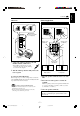
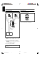
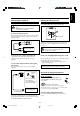
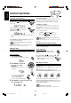
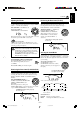
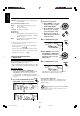
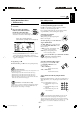
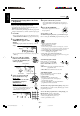
Table Of Contents
- Main body
- Warnings, Cautions and Others
- CAUTION
- IMPORTANT FOR LASER PRODUCTS
- Introduction
- Contents
- Location of the Buttons and Controls
- Getting Started
- Common Operations
- Listening to FM and AM Broadcasts
- Playing Back CDs (CD/CD-R/CD-RW)
- Playing Back Video CDs
- MP3 Disc Playback
- Playing Back Tapes
- Recording
- Using the Microphones
- Using the Timers
- Maintenance
- Troubleshooting
- Specifications
- SP-MXG950V
- SP-MXG850V/SP-MXG880V
- SP-MXG750V
– 7 –
English
1 Connect the AM loop antenna to the AM
LOOP terminals as illustrated.
• If the AM loop antenna wire is covered
with vinyl, remove the vinyl by twisting
it as shown in the diagram.
2 Turn the AM loop antenna until you have the
best reception.
To connect an outdoor AM antenna
When reception is poor, connect a single vinyl-covered wire
to the AM EXT terminal and extend it horizontally. The AM
loop antenna must remain connected.
For better reception of both FM and AM
• Make sure the antenna conductors do not touch any other
terminals and connecting cords.
• Keep the antennas away from metallic parts of the unit,
connecting cords, and the AC power cord.
AM antenna
Vinyl-covered wire
(not supplied)
AM loop antenna
(supplied)
1
2
Connecting Speakers
For Models CA-MXG950V/880V/850V
1 Open the speaker terminals on the rear of the
unit.
2 Insert the end of the speaker cord into the
terminal.
Match the polarity (colours) of the speaker terminals: Red
(+) to red (+) and black (–) to black (–); Blue (+) to blue
(+) and black (–) to black (–).
3 Close the speaker terminals.
IMPORTANT: Use only speakers with the same speaker
impedance as indicated by the speaker terminals on the
rear of the unit.
Blue
1
3
Black
Red
Speaker cords
(blue/black)
Right speaker Left speaker
Speaker cords
(red/black)
Speaker cords
(red/black)
Black
2
Continued
SUBWOOFERMAIN
SUBWOOFER
MAIN
EN01-13.CA-MXG950/850/750 3/1/02, 3:44 PM7