
4ch Network Encoder Instruction Manual

9
Introduction (continued)
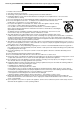
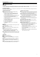
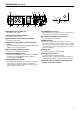
[BACK] [BOTTOM]
M [AUDIO IN] terminal (RCA pin)
For input of audio signals.
N [AUDIO OUT] terminal (RCA pin)
For output of audio signals.
O [VIDEO INPUT 1CH to 4CH] terminal (BNC)
For input of video signals.
P [RS-232C/RS-485] COM1, 2 Protocol Selection
Switch
For switching between RS-232C and RS-485 of COM1 and
COM2. Factory setting is RS-232C.
Q [COM1, COM2] terminal (D-sub 9P)
Serial port for controlling external devices.
R [CONTROL/SERVICE] switch
Switch for switching COM1 to servicing. Select CONTROL
for normal use. Select SERVICE during maintenance.
Factory setting is CONTROL.
S [ALARM OUTPUT] terminal
The COM and OUT terminals form the make contact. Alarm
output changes to break upon turning off the power of
VN-E4, and alarm output is restored to the previous state
upon turning on the power again.
T [ALARM INPUT] terminal
Input terminal for no-voltage make contact or break contact.
This consists of 4 input and 1 ground terminals.
U [10 BASE-T/100 BASE-TX] LAN terminal
For connecting the network cable.
V [RESET] button
Button for resetting VN-E4. Power will be reset upon
pressing this button and releasing it within 5 seconds. If this
button is pressed for 5 seconds or longer, LEDs from STS
to CH4 will start to blink and all settings will be restored to
their factory defaults.
W Wire Clamp
For securing the cable of the AC adaptor.
X [DC 5V] Power Terminal
For connecting the AC adaptor supplied.
VN-E4 does not come with a power switch. It will start up
automatically upon supply of power using the AC adaptor.
Y The MAC address of VN-E4 is displayed on the
label in hexadecimal numbers.
PUSH
ALARM
AUDIO
VIDEO INPUT
IN
OUT
SERVICE
CONTROL
RS-485
RS-232C
INPUT
OUTPUT
COM2
10BASE-T/100BASE-TX
2CH
4CH
3CH
1CH
COM OUT
1234 G
DC 5V
RESET
COM1
M
R
S
TW
U
V
X
N
O
PQ
Y