
Installation Guide

1300 S. Wolf Road • Des Plaines, IL 60018 • Phone 800-323-5068 • Visit us at www.acuitybrands.com/juno-undercabinet
©2017 Acuity Brands Lighting, Inc. Rev 5/17 P5013
2 of 2
INSTALLATION INSTRUCTIONS
Product Services Phone (888) 387-2212
1. Turn off power for appropriate electrical circuit at electrical
service panel.
2. Remove module cover screws and cover. Save screws
and lockwashers.
3. Prepare BX or Flat NM cable (2C+Ground) by stripping
conductor ends approximately 1/2˝.
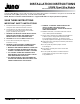
4. For Installation Using NM Cable Push-In Ports: Insert NM
cable through desired PUSH-IN PORT in module as shown.
NM cable outer jacket must protrude thru push-in port to
adequately protect internal conductors. Two ports can be
used for loop-feed supply wiring if desired. Proceed to step 6.
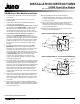
5. For Installation Using 3/8˝ All-Purpose Connector:
Remove desired REAR KNOCKOUT and attach 3/8˝
connector to module as shown. Affix connector to electrical
supply (BX or NM). NM cable outer jacket must protrude thru
connector to adequately protect internal conductors. Tighten
locknut and clamping screws on connector fitting securely.
Two connectors can be used for loop-feed supply wiring
if desired.
6. Determine mounting orientation and remove one SIDE
KNOCKOUT on desired side of module for jumper cord
attachment. The rear knockouts can also be used for jumper
cord attachment if desired. The jumper cord is field
shortenable. Position strain relief bushing on jumper cord
at desired location, compress bushing and insert into module
at SIDE KNOCKOUT. Cut off excess cord and re-strip
conductor ends approximately 1/2˝ for shortened cord
lengths. Leave adequate length for connection to supply
conductors and ground lead.
7. Connect the jumper cord conductors to the supply conductors
and module ground lead using wire nuts provided. Note that
the ribbed side of the jumper cord is the neutral conductor.
The jumper cord center conductor with green insulation is the
ground conductor. If using NM cable, the NM cable must
have a ground wire connected to the module ground lead
and the jumper cord ground conductor. Supply wires are
typically color-coded: hot-black, neutral-white, ground-green
or bare copper.
8. Push excess electrical supply wire back into wall and locate
module on mounting surface. Affix module to underside of
cabinet with screws provided. Be careful not to drive screws
all the way through the cabinet bottom. Use shorter screws
if necessary.
9. Replace and secure module cover with supplied hardware.
Make certain all hardware is replaced and properly tightened.
Make certain lockwashers are located beneath screw heads
to properly ground cover.
10. Follow installation instructions provided with ULH
undercabinet light fixture. Mount fixture, remove electrical
port cover and plug jumper cord (supplied with module) into
electrical port on fixture.
11. Make sure all fixtures connected to the module have their
diffusers/lenses properly installed. Make sure all open
electrical ports on the fixtures are safely enclosed with port
covers provided with fixtures.
12. Restore circuit power at electrical service panel. Turn on
switches at each individual fixture.
UDWM Direct Wire Module Installation
INSTALLATION USING NM CABLE PUSH-IN PORTS
SIDE
KNOCKOUT
NM CABLE
PUSH-IN PORTS
SIDE
KNOCKOUT
FLAT NM CABLE
(2C+GROUND)
SUPPLY WIRE
FIXTURE
PLUG-IN
CONNECTOR
JUMPER CORD,
NEUTRAL SIDE
RIBBED
STRAIN
RELIEF
BUSHING
DIRECT WIRE MODULE
MODULE GROUND
LEAD (GREEN)
WIRE NUT TYP
H H
G
G
N N
G
INSTALLATION USING 3/8˝ ALL-PURPOSE CONNECTOR
REAR KNOCKOUTS
SIDE
KNOCKOUT
SIDE
KNOCKOUT
FIXTURE
PLUG-IN
CONNECTOR
BX OR FLAT
NM CABLE (2C+GROUND)
SUPPLY WIRE
3/8" ALL-PURPOSE
CONNECTOR
GROUND WIRE,
REQUIRED FOR
NM CABLE ONLY
JUMPER CORD,
NEUTRAL SIDE
RIBBED
STRAIN
RELIEF
BUSHING
DIRECT WIRE MODULE
MODULE GROUND
LEAD (GREEN)
WIRE NUT TYP
H H N N
G
G
G
UDWM Direct Wire Module
For use with Juno ULH Series Undercabinet Fixtures