
Installation Guide

JUNO 2" LED RECESSED HOUSINGS
WARNING: For your safety, read and understand instructions completely before starting installation. Before wiring to power supply,
turn off electricity at the fuse or circuit breaker box.
NOTE: Juno recessed fixtures are designed to meet the latest NEC requirements and are listed in full compliance with the relevant UL
standard(s). Before attempting installation of any recessed lighting fixture, check your local electrical building code. This code sets the
wiring standards and installation requirements for your locality and should be understood before starting work. Use of non-Juno trims
voids Juno warranty.
Juno Type IC fixtures are designed for direct contact with
insulating materials which are approved for this application
(Fig. 1). Fixtures may also be used in non-insulated ceilings.
Juno Air-Loc LED housings are supplied with pre-installed
gaskets for energy savings and to comply with energy
code air leakage requirements per ASTM E283.
Product ships with Mounting Frame and LED Trim Module.
Does not include New Construction Plaster Frame (2-NCMF).
SAVE THESE INSTRUCTIONS
THE JUNO 2" LED LUMINAIRES CAN
BE INSTALLED IN MULTIPLE WAYS.
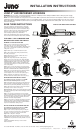
REMODEL STYLE INSTALLATION
Step 1. A precise ceiling opening is required for mounting
of this fixture. The use of a 2 5/8” hole saw is highly
recommended. Fixture can accommodate ceiling thicknesses
from 0.5” to 1”. Use Part No. 2-JCTA150 to accommodate
ceilings from 1” to 1.5”
Step 2. Follow steps 1-4 under Electrical Connection.
Step 3. Slide mounting frame, wiring compartment first,
thru ceiling cut-out (Fig. 2).
Step 4. Align frame over opening so that 4 tabs center
the fixture in the hole (Fig. 3).
Step 5. Pull ceiling clamps back thru ceiling opening.
Position the feet on the room side of the ceiling and tighten
clamping screw to secure the frame to the ceiling. DO NOT
OVER TIGHTEN! The clamps only need to be tight enough
to positively hold the frame in location. Overtightening the
screw will lead to damage to the ceiling and loss of function
of the ceiling clamps.
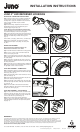
Step 6. Loosen 2 screws and remove top cover from LED
trim module. Plug in connector. DO NOT ALLOW LED TRIM
MODULE TO HANG FROM THIS CONNECTION (Fig. 4).
Step 7. Place connection back into top of LED trim module.
Secure armored cable in “U” shaped opening of top
cover and tighten screws to secure cover in place (Fig. 5).
Step 8. Orient flats of heatsink to the ceiling clamps
and slide module into mounting frame until secure (Fig. 6).
Figure 2
Figure 3
Alignment
Tabs
Ceiling
Clamp
Clamping
Screw
Heatsink
Flat
Rotate
heatsink to
align flats
Figure 6
Ceiling
Clamp
Figure 4 Figure 5
LED Trim
Module
TYPE IC FOR INSULATED CEILINGS
Figure 1
INSTALLATION INSTRUCTIONS
1300 South Wolf Road • Des Plaines, IL 60018 • Phone 800-323-5068 •
Visit us at www.junolightinggroup.com
© 2014 Juno Lighting, LLC. Printed in U.S.A. Rev 5/14 P3697 pg 1 of 2
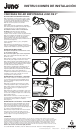
For installation into suspended ceiling, use 2-NCMF
New Construction Mounting Frame accessory.
Step 1. Locate center of proposed opening on ceiling tile
and cut a 2 5/8” hole. An accurate hole is critical for fixture
mounting, a 2 5/8” hole saw is highly recommended.
Step 2. Place ceiling tile in T-bar grid.
Step 3. Place frame into position and snap bar hanger foot
with integral T-bar notch onto T-bars (Fig. 12). Lock in place.
Additional holes are provided for securing with wire or screws
if desired.
Continue with installation from step 2 of the remodel
fixture instructions.
INSTALLATION INTO SUSPENDED CEILING
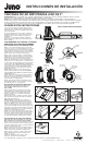
Figure 8
Figure 9Figure 7
Figure 12
Figure 10 Figure 11
Use wire to secure
flex supply to
mounting frame.
Leave adequate
length that can
be pulled thru the
ceiling to attach to
wiring compartment
on the room side
(1’ minimum).
For installation into joist construction, use 2-NCMF
New Construction Mounting Frame accessory.
Step 1. Extend bar hangers to fit between joists. Bar hanger
foot is contoured to easily align with bottom of joist (Fig. 7).
Position fixture by hammering Real-Nails
®
into joists (Fig. 8).
Step 2. Slide frame along bar hangers into desired location.
Use locking screws or slot to secure (Fig. 9).
Relocating Frame – Nail can be removed with hammer claw to
allow easy repositioning of fixture without damaging bar hanger
or nail (Fig. 10).
Step 3. Use steel wire on plaster frame to secure flexible
supply. It is critical that the flex supply is accessible from below
the ceiling where there is no top access to the fixture location
(Fig. 11). Leave adequate length (1' minimum) that can be
pulled into room after ceiling installation.
Step 4. A precise hole is required for mounting of this fixture.
Cutting along the ID of the mounting frame will provide an
accurate hole. After cutting of hole proceed with installation
steps from remodel fixture starting at step 2.
NEW CONSTRUCTION INSTALLATION