
Installation Sheet

SAVE THESE INSTRUCTIONS
JUNO IC1RLED REMODEL RECESSED HOUSINGS
WARNING: For your safety, read and understand instructions completely before starting installation.
Before wiring to power supply, turn off electricity at the fuse or circuit breaker box.
NOTE: Juno recessed fixtures are designed to meet the latest NEC requirements and are listed in full compliance
with the relevant UL standard(s). Before attempting installation of any recessed lighting fixture, check your local
electrical building code. This code sets the wiring standards and installation requirements for your locality and should
be understood before starting work. Use of non-Juno trims voids Juno warranty.
TYPE IC FOR
INSULATED CEILINGS
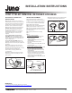
Juno Type IC fixtures are designed for direct
contact with insulating materials that are
approved for this application (Fig. 1). Fixtures
may also be used in non-insulated ceilings.
This Juno Air-Loc LED fixture is supplied
with means to seal the housing after installation
for energy savings and to comply with
energy code air leakage requirements per
ASTM E283.
INSTALLATION STEPS
Note: This housing is compatible with ceiling
thicknesses from 1/2” to 1-1/2” only.
Step 1. Remove optic assembly from carton
and store in a safe place for future installation.
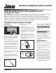
Step 2. Locate center of proposed opening on
ceiling and use template to mark and
accurately cut a 4-3/8” opening (Fig. 2).
Figure 1
FIXTURE DIMMING
Universal Voltage IC1RLED Downlights:
Universal input voltage (120VAC thru 277VAC)
housings. Dimmable with the use of most
0-10V wall box dimmers.
120VAC IC1RLED Downlights: 120VAC
input housings. Dimmable with the use of
most incandescent, magnetic low voltage, or
electronic low voltage* wall box dimmers.
Consult Juno Product Services or website
for compatibility.
*Electronic low voltage dimmers require a
neutral wire connection in the wall box.
OPTIC ASSEMBLY
INSTALLATION
Step 1. After ceiling is finished and painted,
remove and discard paint shield from fixture.
Step 2. Locate the two large raised screws at the
top of the remodel housing. The optic assembly
uses these for retention.
Step 3. Insert optic assembly into housing, with
mounting feet aligned with raised screws. Twist
optic assembly clockwise so mounting feet
engage screws. Twist firmly to lock in place
(Fig. 7).
TRIM INSTALLATION
Insert trim into fixture by lining up trim springs
with the housing opening, and pressing trim up
towards the ceiling. Take note of the position of
the optic within the housing, and avoid contact
with it when pushing in trim.
Figure 2
Step 3. Follow steps 1-4 under Electrical
Connection.
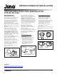
Step 4. Press housing through ceiling opening
until flush to ceiling (Fig. 3). Push retention
clips outward until they click into position. Note:
To remove housing from ceiling, push tab on
clip upward to disengage.
Step 5. To seal housing after confirming
correct operation, apply supplied tape strips to
completely cover each of the three retention
clips and slots. Do not substitute with other
materials (Fig. 4).
Figure 4
Figure 3
Retention
Clips
Tape Strips to
Cover Springs
(3 Places)
INSTALLATION INSTRUCTIONS
1 of 2
1300 S. Wolf Road • Des Plaines, IL 60018 • Phone 800-323-5068 • Visit us at www.acuitybrands.com/juno-recessed
©2017 Acuity Brands Lighting, Inc Rev 3/17 P5912