
Installation Sheet

JUNO IC1RLED REMODEL RECESSED HOUSINGS
ELECTRICAL CONNECTION
INSTRUCTIONS
Step 1. Provide electrical service according to
national and/or local electrical code to the junction
box located on the remodel housing. Supply wire
insulation must be rated for at least 90°C. Note:
this fixture requires a flexible electrical supply.
Step 2. Remove junction box cover. Remove the
appropriate knock-out(s) to accommodate the
type of electrical supply being used. (Fig. 5)
Flexible Metal Conduit. Remove appropriate
round knock-out(s) and connect conduit to
junction box with proper connectors (not
supplied).
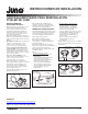
12/2 or 14/2 Non-Metallic Sheathed Cable
(Type NM-B). Remove appropriate D-shaped
cable knock-out(s). Insert the NM-B cable through
the cable trap and make a 90˚L-shaped bend in
cable as shown (Fig. 6).
12/3 or 14/3 Cable (Type NM-B). Remove the
appropriate round knockouts and connect cable
with proper electrical connectors (not supplied and
not shown).
Step 3. Strip supply wire 3/8” and insert each
supply wire into appropriate connector. Connect
black fixture wire to hot, white fixture wire to neutral
and green fixture wire to ground. (Fig. 5).
Connect violet (+) and gray (-) dimmer wires,
( -U models only).
Step 4. Place all wiring and connectors back in
wiring box and replace cover, taking care not to
pinch any wires.
DRIVER REPLACEMENT
Driver replacement must be performed by a
qualified electrician. Before servicing, disconnect
or switch off electrical supply to fixture. Failure to
do so can result in electrical shock and/or injury.
Step 1. Remove trim from fixture.
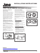
Step 2. Remove optic assembly from housing by
twisting counter-clockwise to unlock. (Fig. 7)
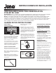
Step 3. Remove tape that seals the three springs.
Disengage remodel springs and remove housing
from ceiling. (Fig. 8)
Step 4. Open junction box to access wiring.
(Fig. 5)
Step 5.
120VAC IC1RLED Downlights:
• Disconnect red and black wires from driver.
• Disconnect driver lead wires from the
supply connections.
• Remove old driver and install new one using
original hardware.
• Re-connect all leads disconnected in
prior steps.
• Close the junction box carefully, taking care not
to pinch any wires.
Universal Voltage IC1RLED Downlights:
• Release all wires from driver by using the quick
disconnect slots located next to each wire.
• Remove old driver and install new one using
original hardware.
• Insert wires into the ports on the new driver.
Note: The red LED lead goes into the black
opening and the black LED lead goes into the
yellow opening on the secondary side.
• Close the junction box carefully, taking care not
to pinch any wires.
Figure 7
Optic
Assembly
Mounting Foot
Raised Screw
Raised Screw
Twist to Lock
into Place
Figure 8
Lift Up Tab
to Disengage
Mounting
Springs
Rotate
Spring Inward
Figure 6
NM-B Cable
Knock-out
(Oval Shaped)
NM-B Cable
Trap
(4 Places)
NM-B Cable
12/2 or 14/2 NM-B Installation
Figure 5
Knock-out
Quick Connector
LED Driver
0-10V
Dimming Wires
(-U models only)
Step 6. Reinstall housing, optic assembly and trim
as previously outlined in this instruction sheet.
INSTALLATION INSTRUCTIONS
2 of 2
1300 S. Wolf Road • Des Plaines, IL 60018 • Phone 800-323-5068 • Visit us at www.acuitybrands.com/juno-recessed
©2017 Acuity Brands Lighting, Inc Rev 3/17 P5912
WARRANTY
5-year limited warranty. Complete warranty terms located at
www.acuitybrands.com/CustomerResources/Terms_and_conditions.aspx
Technical Services Phone (888) 387-2212