
Installation Sheet

ELECTRICAL CONNECTION
INSTRUCTIONS
Step 1. Provide electrical service according to
national and/or local electrical code to the wiring
box located on the fixture plaster frame. Supply wire
insulation must be rated for at least 90°C.
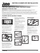
Step 2. Remove wiring box cover. Remove the
appropriate knock-out(s) to accommodate the type
of electrical supply being used (Fig. 8):
Metal Conduit. Remove appropriate round knock-
out(s) and connect conduit to wiring box with proper
connectors (not supplied).
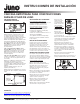
12/2 or 14/2 Non-Metallic Sheathed Cable
(Type NM-B). Remove appropriate D-shaped cable
knock-out(s). Insert the NM-B cable through the
cable trap and make a 90˚L-shaped bend in cable
as shown (Fig. 9).
12/3 or 14/3 Cable (Type NM-B). Remove the
appropriate round knockouts and connect cable
with proper electrical connectors (not supplied and
not shown).
Step 3. Strip supply wire 3/8” and insert each supply
wire into appropriate connector. Connect black fixture
wire to hot, white fixture wire to neutral and green
fixture wire to ground. (Fig. 8).
Connect violet (+) and gray (-) dimmer wires,
( -U models only).
Step 4. Place all wiring and connectors back in
wiring box and replace cover.
FIXTURE DIMMING
Universal Voltage IC1LED Downlights:
Universal input voltage (120VAC thru 277VAC)
housings. Dimmable with the use of most 0-10V
wall box dimmers.
120VAC IC1LED Downlights: 120VAC input
housings. Dimmable with the use of most
incandescent, magnetic low voltage or electronic
low voltage* wall box dimmers.
Consult Juno Product Services or website
for compatibility.
*Electronic low voltage dimmers require a neutral
wire connection in the wall box.
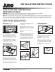
TRIM INSTALLATION
After ceiling is finished and painted, remove
and discard paint shield from fixture.
Insert trim into fixture by lining up trim springs
with the housing opening, and pressing trim up
towards the ceiling. Take note of the position of
the optic within the housing, and avoid contact
with it when pushing in trim.
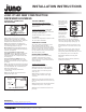
DRIVER REPLACEMENT
Driver replacement must be performed by
a qualified electrician. Before servicing,
disconnect or switch off electrical supply to
fixture. Failure to do so can result in electrical
shock and/or injury.
120VAC IC1LED Downlights:
Step 1. Remove trim from fixture.
Step 2. Pull down inner housing to remove
from fixture. Disconnect red and black wires
connecting driver to inner housing and set
aside. (Fig. 10)
Step 3. Remove junction box cover and
disconnect driver lead wires from supply
connections.
Step 4. Loosen wing nuts and slide driver out
of the mounting bracket. Remove from housing.
(Fig. 11)
Step 5. Install new driver into mounting bracket
and tighten wing nuts to secure in place.
Step 6. Re-connect all leads disconnected in
prior steps.
Figure 9
NM-B Cable
Knock-out
(D-Shaped)
NM-B Cable
Trap
(4 Places)
NM-B Cable
12/2 or 14/2 NM-B Installation
Step 7. Re-install
inner housing and
trim by pushing up
into housing.
Universal Voltage
IC1LED Downlights:
Step 1. Remove
trim from fixture.
Step 2. Pull down
inner housing to
remove from
fixture. (Fig. 10)
Step 3. Remove the wing nuts holding the
driver to the housing. Bring driver (with leads
connected) through ceiling opening. (Fig. 11)
Step 4. Release all wires from driver by using
the quick disconnect slots located next to each
wire.
Step 5. Insert wires into the ports on the new
driver. Note: The red LED lead goes into the
black opening and the black LED lead goes into
the yellow opening on the secondary side.
Step 6. Re-install driver in housing with
wing nuts.
Step 7. Re-install inner housing and trim by
pushing up into housing.
Figure 10
Inner
Housing
Trim
Figure 11
Wing
Nuts
Driver
Figure 8
Knock-
out
Quick
Connector
0-10V Dimming Wires
(-U models only)
JUNO IC1LED NEW CONSTRUCTION
RECESSED HOUSINGS
2 of 2
1300 S. Wolf Road • Des Plaines, IL 60018 • Phone 800-323-5068 • Visit us at www.acuitybrands.com/juno-recessed
©2017 Acuity Brands Lighting, Inc Rev 3/17 P5911
WARRANTY
5-year limited warranty. Complete warranty terms located at
www.acuitybrands.com/CustomerResources/Terms_and_conditions.aspx
Technical Services Phone (888) 387-2212
INSTALLATION INSTRUCTIONS