
Installation Sheet

2 of 2
INSTALLATION INSTRUCTIONS
One Lithonia Way • Conyers, GA 30010 • Phone 1-800-705-SERV (7378) • Visit us at www.acuitybrands.com/juno-recessed
©2020 Acuity Brands Lighting, Inc Rev 05/20 P4745
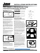
NM-B Cable
Trap
(4 Places)
12/2 or 14/2 NM-B Installation
NM-B Cable
NM-B Cable
Knock-out
(D-Shaped)
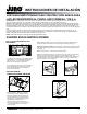
TRIM INSTALLATION
After ceiling is finished and painted, remove and
discard paint shield from fixture. Insert trim into
fixture by lining up trim springs with the housing
opening and pressing trim up towards the ceiling.
Take note of the position of the optic within the
housing and avoid contact with it when pushing in
trim.
WARRANTY
5-year limited warranty. Complete warranty terms located at www.acuitybrands.com/CustomerResources/Terms_and_conditions.aspx
Technical Services Phone 1-800-705-SERV (7378)
JUNO FIREWALL
TM
FIRE RATED LED 4" NEW
CONSTRUCTION RECESSED HOUSINGS
ELECTRICAL CONNECTION
INSTRUCTIONS
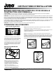
Figure 6
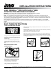
Step 1. Provide electrical service according to
national and/or local electrical code to the wiring box
located on the fixture plaster frame. Supply wire
insulation must be rated for at least 90°C.
Step 2. Remove wiring box cover. Remove the
appropriate knock-out(s) to accommodate the type of
electrical supply being used (Fig. 6):
Metal Conduit. Remove appropriate round knock-
out(s) and connect conduit to wiring box with proper
connectors (not supplied).
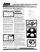
12/2 or 14/2 Non-Metallic Sheathed Cable (Type
NM-B). Remove appropriate D-shaped cable knock-
out(s). Insert the NM-B cable through the cable trap
and make a 90˚L-shaped bend in cable as shown
(Fig. 7).
12/3 or 14/3 Cable (Type NM-B). Remove the
appropriate round knockouts and connect cable
with proper electrical connectors (not supplied and
not shown).
Step 3. Strip supply wire 3/8" and insert each supply
wire into appropriate connector. Connect black fixture
wire to hot, white fixture wire to neutral and green
fixture wire to ground. (Fig. 6).
Connect violet (+) and gray (-) dimmer wires, if
utilizing 0-10V dimmer.
Step 4. Place all wiring and connectors back in
wiring box and replace cover.
Figure 7
FIXTURE DIMMING
Multi-Volt LED 4" Downlights:
Universal input voltage (120VAC thru 277VAC) housings.
Dimmable with the use of most 0-10V wall box dimmers.
120VAC LED 4" Downlights*:
120VAC input housings. Dimmable with the use of most
incandescent, magnetic low voltage or electronic low
voltage** wall box dimmers.
Consult Juno Product Services or website for compatibility.
*WARMDIM
™
is 120VAC only.
**Electronic low voltage dimmers require a neutral wire
connection in the wall box.
DRIVER REPLACEMENT
Driver replacement must be performed by a qualified
electrician. Before servicing, disconnect or switch off
electrical supply to fixture. Failure to do so can result in
electrical shock and/or injury.
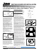
Step 1. Remove trim from fixture.
Step 2. Pull down inner housing to remove from
fixture. Disconnect red and black wires connecting
driver to inner housing and set aside. (Fig. 8)
Step 3. Now access the fixtures wiring by carefully
pulling it through the opening. Once exposed you can
proceed with disconnecting the AC leads that provide
power to the driver and any applicable dimming wires.
Step 4. Lift fire barrier flap on the side with the red and
black wires protruding (red and black wires indicate
driver location). The bottom of the flap will have a half
moon finger slot for easy lifting (Fig. 9). Before lifting
the flap, make sure the wires are pushed out of the
wire slots provided in the flap to prevent tearing the fire
barrier (Fig. 10). This will allow access to the LED
driver.
Step 5. Remove wing nut from driver plate to remove
driver plate from fixture (Fig.11). Pull driver plate out
while slightly lifting to release lower mounting feet.
Once free, pull plate towards fixture opening and rotate
plate 90° so it will fit through fixture opening. Driver
plate rubbing against fire barrier is acceptable.
Step 6. Re-assemble fixture by completing steps 1 thru
5 in reverse order.
JUNCTION BOX ACCESS
Step 1. Remove trim from fixture.
Step 2. Pull down inner housing to remove from fixture.
Disconnect red and black wires connecting driver to
inner housing and set aside (Fig. 8).
Step 3. Now access the fixtures wiring by carefully
pulling it through the opening. Once exposed you can
proceed with disconnecting the AC leads that provide
power to the driver and any applicable dimming wires.
Step 4. Lift fire barrier flap on the side with the red and
black wires protruding (red and black wires indicate
driver location). The bottom of the flap will have a half
moon finger slot for easy lifting (Fig. 9). Before lifting
the flap, make sure the wires are pushed out of the
wire slots provided in the flap to prevent tearing the fire
barrier (Fig. 10). This will allow access to the LED
driver.
Step 5. Open junction box door inside of fixture by
lifting black spring retention clip. Once junction box
door is released pull door out while slightly lifting to
release lower mounting feet. Once free pull plate
towards fixture opening and rotate plate 90° so it will fit
through fixture opening. Junction box door rubbing
against fire barrier is acceptable.
Step 6. Re-assemble fixture by completing steps 1 thru
5 in reverse order.
0-10V Dimming Wires
(-MVOLT models only)
Quick
Connector
Knock-
out
Inner
Housing
Trim
Figure 8
Figure 10
Figure 11
Figure 9
HALF MOON
FINGER SLOT
Box
LED
Driver
WING NUT
Junction