
Installation Instructions

System schemes
6 720 645 817 (2010/09)
8
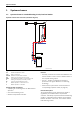
1.3 System scheme 3: mixed heating circuit, DHW circuit, low loss header
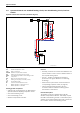
Hydraulic scheme with controller (schematic diagram)
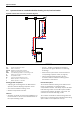
Fig. 3
AF Outside temperature sensor
CUx Boiler control unit
FW 100 Weather-compensated controller
HP Heating circuit pump (primary circuit)
IPM 2 Load switching module for two heating circuits
LP Cylinder primary pump
M 3-way mixer
MF Mixer circuit temperature sensor
P Heating circuit pump (secondary circuit)
SF Cylinder temperature sensor
ST DHW cylinder
TB Temperature limiter
VF Common flow temperature sensor
ZP DHW circulation pump
1 Module position: on the heat source
3 Module position: on the wall
Heating system components
• Suprapur gas condensing boiler for balanced flue
operation
• One mixed heating circuit
• DHW cylinder
• Weather-compensated controller
Features
• Generally, we would recommend the installation of a
low loss header on site to ensure reliable transfer of
the required heating output.
• The FW ... weather-compensated controller is
preferred for its higher utilisation of condensing
technology.
• Determine the system water content and select a
corresponding expansion vessel (Æ page 39).
• Install a mechanical safety limiter (TB 1) in
accordance with the underfloor heating system
manufacturer's instructions.
• Install safety assembly to DIN 1988.
Function description
The mixed heating circuit with low loss header and
DHW heating are regulated by an FW 100 weather-
compensated controller. This always requires the IPM 2
load switching module. A 2-wire BUS system enables
communication between the boiler control unit, the
controller and the load switching module.
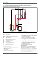
6 720 643 417-03.1O
3
AF
3
CUx 2 MPI001 W
F
T
T
M
M
P
MF
TB
VF
LP
1
ZP
SF
ST ...
Suprapur
KBR 120-280
HP