
Installation Instructions


DHW heating
6 720 645 817 (2010/09)
63
DHW circulation line
Junkers cylinders must be equipped with their own DHW
circulation connection.
Seal this connection if no DHW circulation line is
connected.
DHW circulation is only permitted with reference to the
cool-down losses if a time- and/or temperature-
dependent DHW circulation pump is provided.
Install a suitable non-return valve.
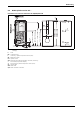
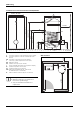
Fig. 37 Connection diagram, DHW side
AV Shut-off valve
DM Pressure reducer (if required, accessory)
E Drain
KW Cold water connection
MAG DHW expansion vessel (recommendation)
MS Pressure gauge connector
PV Test valve
R
SP
Cylinder return
RV Non-return valve
SG Safety assembly to DIN 1988
SV Safety valve
V
SP
Cylinder flow
WW DHW connection
Z DHW circulation connection
ZP On-site DHW circulation pump
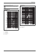
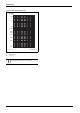
Parallel connection of two cylinders
Fig. 38 Connection in parallel
AV Shut-off valve
DM Pressure reducer (if required, accessory)
E Drain
KW Cold water connection
MS Pressure gauge connector
PV Test valve
R
SP
Cylinder return
RV Non-return valve
S Gate valve
SV Safety valve
V
SP
Cylinder flow
WW DHW connection
Z DHW circulation connection
ZP On-site DHW circulation pump
KW
R
SP
V
SP
6 720 604 132-16.4
O
SG
WW WW
ZP
Z
E
MAG
AV RV DM AV
MS
PV
RV
SV
Parallel connection:
B Connect the cylinders diagonally on the
heating water and DHW sides (according
to the Tichelmann principle).
This balances out different pressure drop
values.
B Only connect one cylinder temperature
sensor.
S
S
S
S
S
S
S
S
R
SP
V
SP
6 720 604 132-15.4O
WW
SV
AV AV
SV
E
KW
Z
RV ZP
E
RV
PV
DM AV
MS