
Installation Instructions

Accessories / Services
6 720 645 817 (2010/09)
48
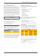
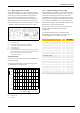
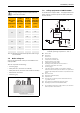
Fig. 30 Residual head no. 1620
H Residual head
V Flow rate
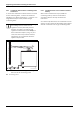
Fig. 31 Dimensions no. 1620 (dim. in mm)
7.2 Pumps
Size pumps in central heating systems in accordance
with current technical rules.
The sizing of pumps to be used on site depends on the
pressure drop of system and boiler (Æ chapter 2.4,
page 29) and the required pump rate.
7.3 Dirt traps
Deposits in heating systems can lead to local
overheating, noise and corrosion. Any resulting boiler
damage falls outside the warranty obligations.
To remove dirt deposits, flush the new heating system
thoroughly prior to installing and commissioning a
boiler. In addition, we recommend the installation of dirt
traps or a blow-down facility.
Dirt traps retain contaminants and thereby prevent
operating faults in control devices, pipework and
boilers. Fit these near the lowest point of the heating
system in an easily accessible position. Clean the dirt
traps every time the heating system is serviced.
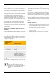
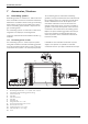
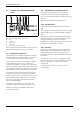
7.4 Low loss header
Subject to the amount of water on the primary and
secondary sides, a lower flow temperature than that
supplied by the boiler itself can be provided if a low loss
header is installed (Æ Fig. 32).
This is the case if the water volume on the secondary
side is greater than that on the primary side. This is used
frequently with gas condensing boilers to prevent a
raising of the return temperature. This leads to a
reduction of the maximum possible flow temperature.
Take this into account when sizing the boiler. For
information, see table 26.
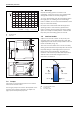
Fig. 32 Use of a low loss header
VF Low loss header sensor
I Primary side
II Secondary side
0
2
4
3
5
6
1
7
0
50
100 150
200
250 300
350 400
V
/ l/min
H
/ m
.
6 720 619 379-56.1O
.
21
Ø12
195
169,5130
82,5
6 720 619 379-57.1O
≤ 85 °C
≤ 75 °C
60 °C
60 °C
ΔT = 25 K
ΔT = 15 K
VF
III
6 720 643 417-25.1O