
Installation Instructions

Engineering information and sizing the heat source
6 720 645 817 (2010/09)
40
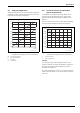
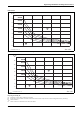
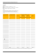
Example 2
Given
n Flow temperature (Æ table 19): ϑ
V
=50°C
o MAG pre-charge pressure (Æ table 19): p
0
=1.00bar
from example 1: system volume: V
A
=4000l
Actual
p A MAG with 200 l capacity is required (Æ table 19), as
the system volume determined in accordance with
Fig. 25 is smaller than the maximum permissible system
volume.
Flow temperature
ϑ
V
Pre-charge pressure
p
0
Diaphragm expansion vessel
80 l 100 l 150 l 200 l
Maximum permissible system volume V
A
°C bar l l l l
90 0.75 960 1200 1800 2400
1.00 850 1050 1575 2100
1.25 705 882 1323 1764
1.50 563 704 1056 1408
80 0.75 1155 1444 2166 2888
1.00 1020 1276 1914 2552
1.25 851 1064 1596 2128
1.50 681 852 1278 1704
70 0.75 1417 1772 2658 3544
1.00 1251 1564 2346 3128
1.25 1043 1304 1956 2608
1.50 835 1044 1566 2088
60 0.75 1792 2240 3360 4480
1.00 1580 1976 2964 3952
1.25 1315 1644 2466 3288
1.50 1052 1316 1974 2632
50 n 0.75 2326 2908 4362 5816
1.00 o 2054 2568 3852 5136 p
1.25 1712 2140 3210 4280
1.50 1369 1712 2568 3424
40 0.75 3107 3884 5826 7768
1.00 2742 3428 5142 6856
1.25 2284 2856 4284 5712
1.50 1827 2284 3426 4568
Tab. 19 Maximum system volume subject to the flow temperature and the required MAG pre-charge pressure.