
Installation Instructions

Specification
6 720 645 817 (2010/09)
24
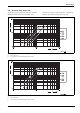
2.2 Dimensions and minimum clearances
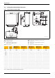
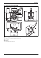
2.2.1 Single appliance Suprapur KBR ...
Fig. 10 Suprapur KBR 120 ... 280-3 A
AA Flue gas connection
AKO Condensate outlet
AL Combustion air pipe connection
(balanced flue operation only)
GAS Gas connection
MAG Connection for diaphragm expansion vessel
RK Boiler return
SV Safety valve or safety assembly connection
VK Boiler flow
1) Not part of the standard boiler delivery
1143
1018
615
100
X
GAS
, X
AL
, X
RK
Z
AA
X
AA
Y
AA
Y
VK
Y
MAG
Ø
AA
GAS
AL
RK
AA
SV
VK
MAG
6 720 643 417-24.1O
AKO
182
176
176
1515
1400
1)
1)
680
496
F
B
34
15 - 25
120
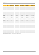
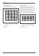
Unit
KBR 120-3 A
MKB 240-3 A
KBR 160-3 A
MKB 320-3 A
KBR 200-3 A
MKB 400-3 A
KBR 240-3 A
MKB 480-3 A
KBR 280-3 A
MKB 560-3 A
B mm 916 1124 1124 1332 1332
Ø
AA
DN 160 160 200 200 200
X
AA
mm 293 345 397 449 501
Y
AA
mm 470 470 495 495 495
Z
AA
mm 145 145 310 310 310
F mm 800 1008 1008 1216 1216
Y
MAG
mm 522 514 514 514 514
Ø
AL
DN 110 110 110 110 110
X
AL
mm 231 335 231 335 231
VK, RK – Rp 2 (DN 50) PN 6 standard flange (DN 65)
X
RK
mm 231 335 231 335 231
Y
VK
mm 1308 1300 1300 1300 1300
SV – R 1 R 1¼
ØGAS – R ¾ R 1½
X
GAS
mm 231 335 231 335 231
Tab. 12 Measurements and connection dimensions