Security Products SSG 140 Hardware Installation and Configuration Guide Juniper Networks, Inc. 1194 North Mathilda Avenue Sunnyvale, CA 94089 USA 408-745-2000 www.juniper.
Copyright Notice Copyright © 2008 Juniper Networks, Inc. All rights reserved. Juniper Networks, the Juniper Networks logo, NetScreen, and ScreenOS are registered trademarks of Juniper Networks, Inc. in the United States and other countries. All other trademarks, service marks, registered trademarks, or registered service marks in this document are the property of Juniper Networks or their respective owners. All specifications are subject to change without notice.
Table of Contents About This Guide 5 Organization .................................................................................................... 6 Conventions..................................................................................................... 6 Web User Interface Conventions .............................................................. 6 Command Line Interface Conventions ......................................................7 Requesting Technical Support ..........................
SSG 140 Series Hardware Installation and Configuration Guide Hostname and Domain Name .................................................................28 Domain Name System Server.................................................................. 28 Date and Time......................................................................................... 28 Default Route........................................................................................... 29 Bridge Group Interfaces ........................
About This Guide The Juniper Networks Secure Services Gateway (SSG) 140 devices is an integrated router and firewall platform. It provides Internet Protocol Security (IPSec) virtual private network (VPN) and firewall services for small- and medium-sized companies and enterprise branch and remote offices. NOTE: The configuration instructions and examples in this document are based on the functionality of a device running ScreenOS 6.0.0.
SSG 140 Series Hardware Installation and Configuration Guide Organization This guide contains the following chapters and appendixes: Chapter 1, “Hardware Overview,” describes the chassis and components of the SSG 140 device. Chapter 2, “Installing and Connecting the Device,” describes how to mount the SSG 140 device in a standard 19-inch equipment rack and how to connect cables and power to it.
About This Guide option from the list and follow the instructions on the page. Click the ? character in the upper left for Online Help on the Config Guide. Command Line Interface Conventions The following conventions are used to present the syntax of command line interface (CLI) commands in text and examples. In text, commands are in boldface type and variables are in italic type. In examples: Variables are in italic type. Anything inside square brackets [ ] is optional.
SSG 140 Series Hardware Installation and Configuration Guide Find CSC offerings—http://www.juniper.net/customers/support/ Find product documentation—http://www.juniper.net/techpubs/ Find solutions and answer questions using our Knowledge Base— http://kb.juniper.net/ Download the latest versions of software and review your release notes— http://www.juniper.net/customers/csc/software/ Search technical bulletins for relevant hardware and software notifications— http://www.juniper.
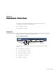
Chapter 1 Hardware Overview This chapter provides detailed descriptions of the SSG 140 device and its components. It contains the following sections: “Front Panel” on page 9 “Back Panel” on page 13 Front Panel Figure 1 shows the front panel of the SSG 140 device.
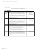
SSG 140 Series Hardware Installation and Configuration Guide Port Descriptions Table 1 describes the function, connector type, and speed/protocol (if applicable) of the ports on the front panel of the SSG 140 device. Table 1: SSG 140 Ports Item Description Ethernet 0/0 to Enables ethernet connections to workstations or a LAN connection 0/7 Ports through a switch or hub. These connections also allow you to manage the device through a Telnet session or the WebUI.
Chapter 1: Hardware Overview Device Status LEDs The device LEDs show information about current device status. Figure 2 shows the position of each LED on the front of the SSG 140 device. Figure 2: Device Status LEDs When the device powers up, the POWER LED changes from off to green and the STATUS LED changes from off to blinking green. Startup takes approximately one minute to complete.
SSG 140 Series Hardware Installation and Configuration Guide Ethernet Port LEDs The Ethernet LEDs show the status of each Ethernet port. Figure 3 shows the location of the LEDs on each Ethernet port. Figure 3: Ethernet Port LEDs TX/RX LINK Table 3 describes the Ethernet port LEDs. Table 3: Ethernet Port LEDs Name Function Color State Description LINK Link Green On steadily Port is online. Off Port is offline. TX/RX Activity Green Blinking Port is receiving data.
Chapter 1: Hardware Overview 2. Save the files from the USB storage device to the internal flash storage on the device with the save {software | config | image-key} from usb filename to flash command. 3. Stop the USB port with the exec usb-device stop command before removing the USB storage device. CAUTION: Always execute the exec usb-device stop command before disconnecting a USB storage device. Disconnecting a USB device without executing the stop command may cause the device to restart. 4.
SSG 140 Series Hardware Installation and Configuration Guide CAUTION: PIMs are not hot-swappable. Always switch off the device before inserting or removing PIMs. Power Switch The power switch is located on the right side of the back panel, as shown in Figure 5. You use the power switch to power the SSG 140 device on and off. When you power on the device, ScreenOS starts up as the power supply completes its startup sequence.
Chapter 2 Installing and Connecting the Device This chapter describes how to install an SSG 140 device in a standard 19-inch equipment rack and how to connect cables and power to the device.
SSG 140 Series Hardware Installation and Configuration Guide Before You Begin The location of the chassis, the layout of the equipment rack, and the security of your wiring room are crucial for proper device operation. CAUTION: To prevent abuse and intrusion by unauthorized personnel, install the SSG 140 device in a secure environment.
Chapter 2: Installing and Connecting the Device To install an SSG 140 device into a rack: 1. Attach the mounting brackets to each side of the chassis as shown in Figure 6. For front mounting, use the holes nearest the front of the device. For center-mounting, use the holes nearest the center of each side of the device. Figure 6: Attaching Rack Mount Brackets (Front-Mount Shown, Center-Mount Similar) 2. Grasp the sides of the device, lift the device, then position it in the rack.
SSG 140 Series Hardware Installation and Configuration Guide Organizing Interface Cables Arrange network cables as follows to prevent them from dislodging or developing stress points: Secure cables so that they are not supporting their own weight as they hang to the floor. Place excess cable out of the way in neatly coiled loops. Use fasteners to maintain the shape of cable loops.
Chapter 2: Installing and Connecting the Device 3. Connect an RJ-45 cable from the port labeled 0/2 (ethernet0/2 interface) to the external switch or router. The ethernet0/2 interface is prebound to the Untrust security zone. 4. Connect an RJ-45 cable from the Console port using the instructions provided in “Using a Console Connection” on page 22 for management access.
SSG 140 Series Hardware Installation and Configuration Guide 20 Connecting the Device to a Network
Chapter 3 Configuring the Device ScreenOS software is preinstalled on the SSG 140 device. When the device is powered on, it is ready to be configured. While the device has a default factory configuration that allows you to initially connect to the device, you must perform further configuration for your specific network requirements.
SSG 140 Series Hardware Installation and Configuration Guide Accessing the Device You can configure and manage the SSG 140 device in several ways: Console—The Console port on the device lets you access the device through a serial cable connected to your workstation or terminal. To configure the device, you enter ScreenOS command line interface (CLI) commands on your terminal or in a terminal-emulation program on your workstation. For more information, see “Using a Console Connection” on page 22.
Chapter 3: Configuring the Device 3. Plug the other end of the RJ-45 CAT5 cable into the Console port on the SSG 140. Figure 9 shows the arrangement of the cable and adapter. Figure 9: Establishing a Console Connection DB-9 adapter Serial port on workstation CAT5 RJ-45 cable Console port on SSG 140 4. Launch a serial terminal-emulation program on your workstation.
SSG 140 Series Hardware Installation and Configuration Guide Using the WebUI To use the WebUI, the workstation from which you are managing the device must initially be on the same subnetwork as the device. To access the device with the WebUI: 1. Connect your workstation to the port labeled 0/0 (ethernet0/0 interface), which is prebound to the Trust security zone. 2. Ensure that your workstation is configured with a static IP address in the 192.168.1.0/24 subnet. 3.
Chapter 3: Configuring the Device 5. (Optional) By default, the console times out and terminates automatically after 10 minutes of idle time. To prevent the console from timing out and terminating automatically, enter set console timeout 0. Default Device Settings Table 4 describes the default interface-to-zone bindings on the SSG 140 device. Table 4: Default Interface-to-Zone Bindings Port Label Interface Zone 0/0 (default IP address is 192.168.1.
SSG 140 Series Hardware Installation and Configuration Guide Basic Device Configuration The following sections describe the basic configuration tasks required to place the SSG 140 device in operation.
Chapter 3: Configuring the Device Administrative Access By default, anyone on your network who knows the login and password can manage your device. To configure a device to be managed only from a specific host on your network: WebUI Configuration > Admin > Permitted IPs: Enter the following, then click Add: IP Address/Netmask: ip_addr/mask CLI set admin manager-ip ip_addr/mask save Interface IP Address The ethernet0/0 interface has the default IP address 192.168.1.
SSG 140 Series Hardware Installation and Configuration Guide Hostname and Domain Name The domain name defines the network or subnetwork that the device belongs to, while the hostname refers to a specific device. The hostname and domain name together uniquely identify a device in the network.
Chapter 3: Configuring the Device WebUI 1. Configuration > Date/Time: Click the Sync Clock with Client button. A pop-up message prompts you to specify if you have enabled the daylight saving time option on your workstation clock. 2. Click Yes to synchronize the device clock and adjust it according to daylight saving time, or click No to synchronize the device clock without adjusting for daylight saving time.
SSG 140 Series Hardware Installation and Configuration Guide To configure a bridge group: WebUI Network > Interfaces > List > Edit (bgroup0) > Bind Port: Select ethernet0/3, ethernet0/4, and ethernet0/5, then click Apply. >Basic: Enter the following, then click Apply: Zone Name: DMZ (select) IP Address/Netmask: 10.0.0.
Chapter 3: Configuring the Device The device applies firewall policies, which can contain content filtering and Intrusion Detection and Prevention (IDP) components, to the traffic that passes the Screen filters from one zone to another. By default, no traffic is permitted to pass through the device from one zone to another. To permit traffic to cross the device from one zone to another, you must create a policy that overrides the default behavior.
SSG 140 Series Hardware Installation and Configuration Guide 2. If you have not yet changed the default username and password, enter netscreen at both the login and password prompts. (Use lowercase letters only. The login and password fields are both case-sensitive.) 3. At the console prompt, enter: reset The device prompts you to confirm the reset: System reset, are you sure? y/[n] 4. Enter Y. The device restarts. Restarting the Device with the WebUI To restart the device with the WebUI: 1.
Chapter 3: Configuring the Device NOTE: By default, the device recovery feature is enabled. You can disable it by entering the CLI unset admin device-reset command. Also, if the security device is in FIPS mode, the recovery feature is automatically disabled.
SSG 140 Series Hardware Installation and Configuration Guide 2. At the command prompt, enter unset all. The following message is displayed: Erase all system config, are you sure y/[n] ? 3. Press y 4. Enter reset. Press n for the first question and y for the second question: Configuration modified, save? [y]/n System reset, are you sure? y/[n] The system now resets and returns to the login prompt; the default login name and password are both reset to netscreen.
Chapter 3: Configuring the Device 3. Release the pinhole button, and wait two seconds. 4. Push the pinhole button again for four to six seconds. The message “2nd push has been confirmed” appears. 5. Continue to press the pinhole button until the device resets. The system now resets and returns to the login prompt; the default login name and password are both reset to netscreen.
SSG 140 Series Hardware Installation and Configuration Guide 36 Resetting the Device to Factory Defaults
Chapter 4 Servicing the Device This chapter describes service and maintenance procedures for the SSG 140 device. It includes the following topics: NOTE: “Tools and Parts Required” on page 37 “Replacing a PIM” on page 38 “Upgrading Memory” on page 40 “Replacing the Fuse” on page 43 For safety warnings and instructions, refer to the Juniper Networks Security Products Safety Guide. The instructions in the guide warn you about situations that could cause bodily injury.
SSG 140 Series Hardware Installation and Configuration Guide Replacing a PIM The SSG 140 device has four PIM slots in the back panel. PIMs are field installable and replaceable. CAUTION: Power off the device before removing or installing PIMs. PIMs are not hot-swappable. Removing a Blank Faceplate To maintain proper airflow through the device, blank faceplates should remain over slots that do not contain PIMs. Do not remove blank faceplates unless you are installing a PIM in the empty slot.
Chapter 4: Servicing the Device Removing a PIM To remove a PIM: 1. Place an electrostatic bag or antistatic mat on a flat, stable surface on which you intend to place the PIM. 2. Attach an ESD grounding strap to your bare wrist, and connect the strap to an ESD point on the device. 3. If the device is powered on, switch off the power switch on the back of the device. Verify that the POWER LED is off. 4. Label the cables connected to the PIM so that you can later reconnect each cable to the correct PIM. 5.
SSG 140 Series Hardware Installation and Configuration Guide Installing a PIM To install a PIM: 1. Attach an ESD grounding strap to your bare wrist, and connect the strap to the ESD point on the device. 2. If the device is powered on, switch off the power switch on the back of the device. Verify that the POWER LED is off. 3. Grasp the handles on each side of the PIM faceplate. On some PIMs the handles are metal ears attached to the PIM faceplate. Other PIMs have long screws that serve as the handles. 4.
Chapter 4: Servicing the Device To determine the amount of memory, use the get sys command. The command response shows the amount of memory installed. NOTE: The SSG 140 device must have 512 MB of memory installed to run the following ScreenOS Unified Threat Management (UTM) features: Antivirus Antispam Web filtering Intrusion Prevention System (IPS) To upgrade the memory on the SSG 140 device: 1.
SSG 140 Series Hardware Installation and Configuration Guide Figure 12: Memory Module Slot Rear Memory module slot Front 10. Release the 256 MB memory module by pressing your thumbs downward on the locking tabs on each side of the module so that the tabs swivel away from it. 11. Grip the long edge of the memory module and slide it out. Set it aside. Figure 13: Releasing and Removing the Memory Module 12. Insert the 512 MB memory module into the slot from which you removed the 256 MB memory module.
Chapter 4: Servicing the Device 13. To replace the top panel on the chassis, set the rear edge of the top panel into the groove that runs along the top rear edge of the chassis. Then lower the top panel onto the chassis. 14. Slide the top panel back 1/2-inch (13mm). 15. Use the number-2 phillips screwdriver to replace and tighten the screws you removed earlier, securing the top panel to the chassis. 16.
SSG 140 Series Hardware Installation and Configuration Guide 3. Manually remove the fuse assembly from the device. 4. To replace the fuse assembly, enter the new fuse into the opening and slide it in until the fuse clicks into place. 5. Replace the power cable and turn the device power switch ON. Reconnect the network cables.
Appendix A Specifications This appendix provides general specifications for the SSG 140 device. It contains the following sections: “Physical” on page 45 “Electrical Specifications” on page 46 “Environmental Tolerance” on page 46 “Certifications” on page 47 “Connectors” on page 48 Physical Table 5 provides the physical specifications for the SSG 140 device. Table 5: SSG 140 Physical Specifications Description Value Chassis dimensions 1.75 inches (4.4 cm) high 17.5 inches (44.
SSG 140 Series Hardware Installation and Configuration Guide Electrical Specifications Table 6 provides the electrical specifications for the SSG 140 device. Table 6: SSG 140 Electrical Specifications Item Specification AC input voltage Operating range: 90 to 264 VAC AC input line frequency 50 or 60 Hz AC device current rating 1.8A Environmental Tolerance Table 7 provides the environmental tolerance for the SSG 140 device.
Appendix A: Specifications Certifications Table 8 provides the device certifications for the SSG 140 device. Table 8: SSG 140 Device Certifications Certification Type Certification Name Safety CAN/CSA-C22.2 No.
SSG 140 Series Hardware Installation and Configuration Guide Connectors Figure 15 shows the pin numbering of the RJ-45 connectors for the Console and AUX ports. Figure 15: RJ-45 Connector Pin Numbering 1 8 Table 9 lists the pinouts of the RJ-45 connectors for the Console and AUX ports.
Appendix A: Specifications Figure 16 shows the pin numbering of the connector on the DB-9 adapter supplied with the device. Figure 16: DB-9 Connector Pin Numbering Table 10 lists the pinouts for the DB-9 adapter.
SSG 140 Series Hardware Installation and Configuration Guide The E1 and T1 PIMs use RJ-48 cables, which are not supplied with the PIM. Table 12 describe the RJ-48 connector pinouts. CAUTION: To maintain agency approvals, use only properly constructed, shielded cables.
Appendix B Initial Configuration Wizard This appendix provides detailed information about the Initial Configuration Wizard (ICW) for an SSG 140 device. After you have physically connected your device to the network, you can use the ICW to configure the interfaces that are installed on your device. This section describes the following ICW windows: 1. Rapid Deployment Window on page 52 2. Administrator Login Window on page 52 3. Physical Ethernet Interface Window on page 53 4.
SSG 140 Series Hardware Installation and Configuration Guide 1. Rapid Deployment Window Figure 17: Rapid Deployment Window If your network uses Network and Security Manager (NSM), you can use a Rapid Deployment configlet to automatically configure the device. Obtain a configlet from your Security Manager administrator, select the Yes option, select the Load Configlet from: option, browse to the file location, then click Next. The configlet sets up the device for you.
Appendix B: Initial Configuration Wizard 3. Physical Ethernet Interface Window On the interface-to-zone bindings screen, you set the interface to which you want to bind the Untrust security zone. Ethernet0/0 is prebound to the Trust security zone. Ethernet0/1 is bound to the DMZ security zone but is optional. Ethernet0/2 is bound to the Untrust zone. Figure 19: Physical Ethernet Interface Window After binding an interface to a zone, you can configure the interface.
SSG 140 Series Hardware Installation and Configuration Guide 4. Untrust Zone Window The Untrust zone interface can have a static IP address or a dynamic IP address assigned via DHCP. Insert the desired information, then click Next. Figure 20: Untrust Zone Window Table 13: Field Descriptions for Ethernet0/0 Interface 54 Field Description Dynamic IP via DHCP Enables the device to receive an IP address for the Untrust zone interface from an ISP.
Appendix B: Initial Configuration Wizard 5. DMZ Interface IP Address Window Use this screen to configure an IP address and a netmask for the DMZ interface. Figure 21: DMZ Interface IP Address Window 6. Trust Interface IP Address Window Use this screen to configure an IP address and a netmask for the Trust interface.
SSG 140 Series Hardware Installation and Configuration Guide 7. Physical Ethernet DHCP Interface Window Select Yes to enable your device to assign IP addresses to your wired network via DHCP. Enter the IP address range that you want your device to assign to clients using your network, then click Next.
Appendix B: Initial Configuration Wizard 8. Confirmation Window Confirm your device configuration and change as needed. Click Next to save, restart the device, and run the configuration. Figure 24: Confirmation Window After the device restarts with the saved system configuration, the WebUI login prompt appears. For information about accessing the device using the WebUI, see “Using the WebUI” on page 24.
SSG 140 Series Hardware Installation and Configuration Guide 58
Index A access, configuring administrative ..............................27 addresses, default IP .....................................................25 admin name and password, changing ........................26 administrative access, configuring ..............................27 ALARM LED ....................................................................11 B back-panel components................................................13 basic configuration .....................................................
SSG 140 Hardware Installation and Configuration Guide power, connecting ......................................................... 18 R racks, installing .............................................................. 16 removing faceplates ................................................................. 38 PIMs .......................................................................... 39 Reset/Reset Config button ............................................ 34 resetting to factory defaults ...............