
Datasheet
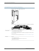


Type 4 PIC
•
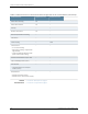
One 100-Gigabit Ethernet port
•
Power requirements for PD-1CE-CFP-FPC4 (PIC and FPC): 9.48 A @48 V (455 W)
•
Model number: PD-1CE-CFP-FPC4
•
PIC 0 and PIC 1 are connected by a bridge board.
•
There are two physical interfaces when the 100-Gigabit Ethernet PIC is online. Each physical
interface represents one of two internal 50-Gigabit Ethernet Packet Forwarding Engines (PFEs)
in the FPC. PFE0 is physical interface 0, PFE1 is physical interface 1.
The following example shows the CLI representation of the physical interface. The interface
type is et, fpc is the FPC slot number, the PIC slot is always 0, and the PFEs are 0:0 for PFE0
and 0:1 for PFE1.
•
et-fpc/0/0:0
•
et-fpc/0/0:1
•
You must also configure two logical interfaces under each physical interface. The following
CLI example shows the logical interfaces.
•
et-fpc/0/0:0.0 and et-fpc/0/0:0.1
•
et-fpc/0/0:1.0 and et-fpc/0/0:1.1
NOTE: For more information about CLI commands, see Ethernet Interfaces.
NOTE: When bringing the PIC online and offline using the request chassis pic (offline | online)
fpc-slot slot-number pic-slot slot-number command, you must specify pic-slot slot-number 0. See
request chassis pic.
•
Support for MTUs up to 9192 bytesHardware features
93Copyright © 2013, Juniper Networks, Inc.
100-Gigabit Ethernet PIC with CFP (T4000 Router)