
manual


Table Of Contents
- Introduction
- Scope
- Design Considerations—Connectivity at the Branch Office
- Branch-Office Connectivity over IPsec VPN
- Design Recommendations
- Routing Information Protocol
- Traffic Load Balancing for Type B and Type C Branch Deployments
- Using Border Gateway Protocol for Large Networks
- Using OSPF for Small Number of Branch Offices
- Using Auto Connect VPN to Create Branch-to-Branch IPsec Tunnels
- High Availability for the Branch Office
- High Availability Requirement Levels (Link, Device, Device, and Link Levels)
- High Availability Functionalities
- High Availability for Branch Office Type A
- VPN Security Zone Configuration for Type A
- High Availability for Branch Office Type B
- Using Secure Services Gateway for Type B
- High Availabilty for Branch Office Type C
- Connectivity at the Data Center
- Implementing a High Availability Enterprise Network at the Data Center
- Quality of Service Design Requirements
- WX Design Requirements
- Summary
- Appendix A Related Documents
- Appendix B Naming Conventions
- Appendix C Products
- About Juniper Networks
- Figure 1: Connecting branch offices, campus locations, and data centers over a single converged network
- Figure 2: Branch office reference architecture
- Figure 3: Multi-tiered/layered network architecture
- Figure 4: Two-tier network design for data centers
- Figure 5: Branch with dual internet connections (load balancing using ECMP)
- Figure 6: BGP routing design
- Figure 7: Star topology – connecting branches to central hub
- Figure 8: AC VPN provisioned tunnels between branches in the same region
- Figure 9: Multi-tier topology
- Figure 10: HA configuration for Type A
- Figure 11: VPN security zone configuration for Type A
- Figure 12: Type B optimized – HA configuration
- Figure 13: Type B – security zones
- Figure 14: Type C – HA configuration
- Figure 15: Intra-branch using OSPF
- Figure 16: Branch Type C – security zones
- Figure 17: Enterprise network for the data center
- Figure 18: M Series Multiservice Edge Routers
- Figure 19: Internet firewalls
- Figure 20: VPN firewalls
- Figure 21: VPN firewall IPS policy
- Figure 2: Branch office reference architecture
Copyright © 2010, Juniper Networks, Inc. 5
APPLICATION NOTE - Branch Office Connectivity Guide
When a device sends traffic to other devices, it sends the traffic to an upper layer router. The process repeats until
the traffic arrives at the specified router with visibility to forward the traffic down to a lower layer. Because devices
on the top layer are usually fully meshed, they can send the traffic to the appropriate router. The traffic is then
forwarded down the layer chain until it reaches its final destination.
The obvious advantage of using a tiered layer approach is scalability. Any-to-any connectivity is required only for routers
on the higher layer. Routers on lower layers require only a single connection (although for redundancy purposes it is
common to provide more than one). This scalable approach reduces the minimum topology to a tree topology whereby
each device requires only one or two connections (except for the devices on the top-most layer), effectively reducing the
traditional scalability challenge to a linear function bound to the number of devices in the network.
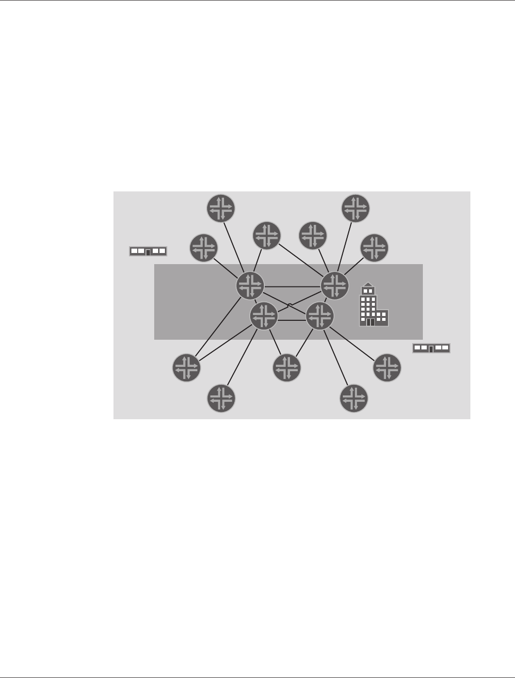
Considering enterprises’ scalability requirements, a two-tier design is sufficient to accommodate network needs.
Because each VPN concentrator can terminate in excess of 2,000 tunnel connections, there is no need to further
segment the design.
The resulting topology consists of a set of remote branches interconnected through a tier of data centers (or regional
offices), as shown in Figure 4.
Figure 4: Two-tier network design for data centers
Note: Whenever traffic patterns require a hybrid design, Juniper Networks recommends using Auto Connect VPN
(AC VPN). As an example, AC VPN is well suited if the group of branches has high demands of inter-branch traffic.
The AC VPN feature can ease the provisioning burden while providing full-mesh connectivity. For further details
concerning AC VPN, see Using AC VPN to Create Branch-to-Branch IPsec Tunnels.
The proposed two-tier network design refers to the topology of the overlay IPsec network and not to the underlying
physical network. Physically, the network resembles the diagram, as shown in Figure 2, Branch Office Reference
Architecture.
Routing Information Protocol
Several designs for the routing topology were considered. On one side, a robust, scalable, and standards-based
solution is desired. On the other side, ease of configuration and deployment is more appealing (considering the large
number of sites expected). To address these concerns, different routing protocols (RIP, BGP, and OSPF) are discussed
with their associated benefits and problems. For further details concerning BGP, see Using BGP for Large Networks.
Juniper Networks recommends RIP as the routing protocol for enterprise networks that connect between 100
to 1,000 branch office locations. Using a RIP-based IPsec routing implementation provides a cost-effective and
secure alternative when employing leased lines and other expensive L2 networking technologies. However, some
of the challenges as well as the trade-offs of each design decision are presented here. The proposed routing
architecture’s goal is to balance complex implementation with design scalability, but still be well-suited for small to
medium-sized organizations.
TIER-1TIER-2