
manual


Table Of Contents
- Introduction
- Scope
- Design Considerations—Connectivity at the Branch Office
- Branch-Office Connectivity over IPsec VPN
- Design Recommendations
- Routing Information Protocol
- Traffic Load Balancing for Type B and Type C Branch Deployments
- Using Border Gateway Protocol for Large Networks
- Using OSPF for Small Number of Branch Offices
- Using Auto Connect VPN to Create Branch-to-Branch IPsec Tunnels
- High Availability for the Branch Office
- High Availability Requirement Levels (Link, Device, Device, and Link Levels)
- High Availability Functionalities
- High Availability for Branch Office Type A
- VPN Security Zone Configuration for Type A
- High Availability for Branch Office Type B
- Using Secure Services Gateway for Type B
- High Availabilty for Branch Office Type C
- Connectivity at the Data Center
- Implementing a High Availability Enterprise Network at the Data Center
- Quality of Service Design Requirements
- WX Design Requirements
- Summary
- Appendix A Related Documents
- Appendix B Naming Conventions
- Appendix C Products
- About Juniper Networks
- Figure 1: Connecting branch offices, campus locations, and data centers over a single converged network
- Figure 2: Branch office reference architecture
- Figure 3: Multi-tiered/layered network architecture
- Figure 4: Two-tier network design for data centers
- Figure 5: Branch with dual internet connections (load balancing using ECMP)
- Figure 6: BGP routing design
- Figure 7: Star topology – connecting branches to central hub
- Figure 8: AC VPN provisioned tunnels between branches in the same region
- Figure 9: Multi-tier topology
- Figure 10: HA configuration for Type A
- Figure 11: VPN security zone configuration for Type A
- Figure 12: Type B optimized – HA configuration
- Figure 13: Type B – security zones
- Figure 14: Type C – HA configuration
- Figure 15: Intra-branch using OSPF
- Figure 16: Branch Type C – security zones
- Figure 17: Enterprise network for the data center
- Figure 18: M Series Multiservice Edge Routers
- Figure 19: Internet firewalls
- Figure 20: VPN firewalls
- Figure 21: VPN firewall IPS policy
- Figure 2: Branch office reference architecture
4 Copyright © 2010, Juniper Networks, Inc.
APPLICATION NOTE - Branch Office Connectivity Guide
• Configuration Simplicity: Provisioning is easy. When the number of sites is large, it is important to reduce the
complexity of the configuration on a per-site basis, where possible. That is, requiring multiple configurations
should be as simple as possible.
• Link-Failure Detection: Link-failure detection mechanisms are required. Because IPsec tunnels use a Layer 3
infrastructure, routing (and sometimes link routing) failures are possible where the tunnel termination points
are not notified of the malfunction. Therefore, the control and data plane keep-alive protocols should be used to
detect the malfunctions.
• Unified Threat Management (UTM): UTM features and firewalls should be enabled at the branches. For both
to function properly, it is mandatory to guarantee that both ingress and egress traffic flows across the same
firewall. The same is true for data centers. Traffic symmetry enforcement is required to ensure that each
particular traffic flow (and sometimes groups of flows, as is the case with protocols that use more than one
connection) is presented across the same set of inspection devices.
Routing Architecture
To ensure connectivity, a minimum of one IPsec tunnel between each branch office and the central office is required.
With N remote locations, a full mesh of tunnels would equal N*(N-1)/2 total tunnels. In particular, if implementing a
VPWAN solution (having 1,000 sites), this solution requires a minimum of 499,550 tunnels. Clearly, it would not only
be quite difficult to manage but also requires each branch to terminate at least 999 tunnels.
Note: Enterprise networks in general have an asymmetric traffic profile—that is, most of the internal traffic travels
from the branches to the data center and vice versa. Generally, traffic between branches does not constitute the bulk
of the traffic carried across the network.
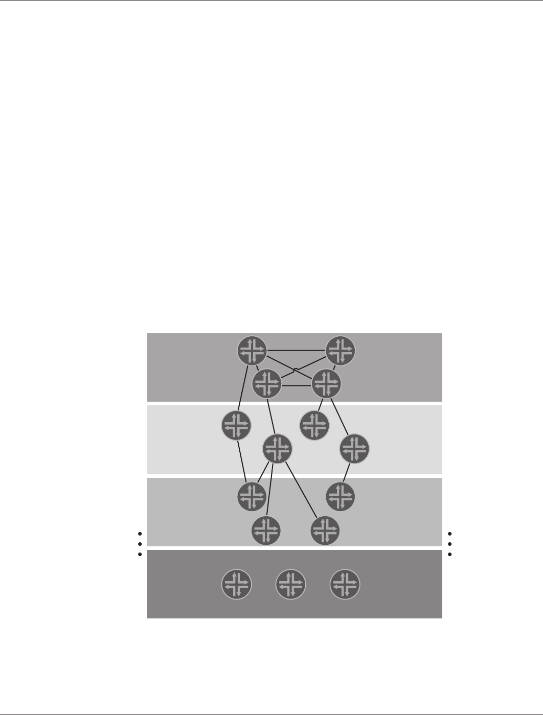
Tiered Network Approach—Layering the Network for Scalability
To circumvent the N2 scalability problem, it is customary to partition the network into several layers. Devices on each
layer connect only to devices located on an upper and lower layer, as shown in Figure 3.
Figure 3: Multi-tiered/layered network architecture
TIER-1
TIER-2
Device
(n-1)
Device N
Device 1
TIER-3
TIER-N
Device 2