
manual


Table Of Contents
- Introduction
- Scope
- Design Considerations—Connectivity at the Branch Office
- Branch-Office Connectivity over IPsec VPN
- Design Recommendations
- Routing Information Protocol
- Traffic Load Balancing for Type B and Type C Branch Deployments
- Using Border Gateway Protocol for Large Networks
- Using OSPF for Small Number of Branch Offices
- Using Auto Connect VPN to Create Branch-to-Branch IPsec Tunnels
- High Availability for the Branch Office
- High Availability Requirement Levels (Link, Device, Device, and Link Levels)
- High Availability Functionalities
- High Availability for Branch Office Type A
- VPN Security Zone Configuration for Type A
- High Availability for Branch Office Type B
- Using Secure Services Gateway for Type B
- High Availabilty for Branch Office Type C
- Connectivity at the Data Center
- Implementing a High Availability Enterprise Network at the Data Center
- Quality of Service Design Requirements
- WX Design Requirements
- Summary
- Appendix A Related Documents
- Appendix B Naming Conventions
- Appendix C Products
- About Juniper Networks
- Figure 1: Connecting branch offices, campus locations, and data centers over a single converged network
- Figure 2: Branch office reference architecture
- Figure 3: Multi-tiered/layered network architecture
- Figure 4: Two-tier network design for data centers
- Figure 5: Branch with dual internet connections (load balancing using ECMP)
- Figure 6: BGP routing design
- Figure 7: Star topology – connecting branches to central hub
- Figure 8: AC VPN provisioned tunnels between branches in the same region
- Figure 9: Multi-tier topology
- Figure 10: HA configuration for Type A
- Figure 11: VPN security zone configuration for Type A
- Figure 12: Type B optimized – HA configuration
- Figure 13: Type B – security zones
- Figure 14: Type C – HA configuration
- Figure 15: Intra-branch using OSPF
- Figure 16: Branch Type C – security zones
- Figure 17: Enterprise network for the data center
- Figure 18: M Series Multiservice Edge Routers
- Figure 19: Internet firewalls
- Figure 20: VPN firewalls
- Figure 21: VPN firewall IPS policy
- Figure 2: Branch office reference architecture
2 Copyright © 2010, Juniper Networks, Inc.
APPLICATION NOTE - Branch Office Connectivity Guide
Design Considerations—Connectivity at the Branch Office
In this section, design guidance for the following major topics is presented:
• Implementing branch office connectivity using an IPsec VPN overlay
• Using RIP as the preferred routing protocol for the solution
• Employing address traffic load balancing
• Considering additional routing protocols other than RIP for the same design model
After defining the basic design for branch office connectivity, guidance and solutions are presented for configuring
HA and fault tolerance for all three types of branch office profiles: Type A, Type B, and Type C. The first section
defines the enterprise network architecture at a high level.
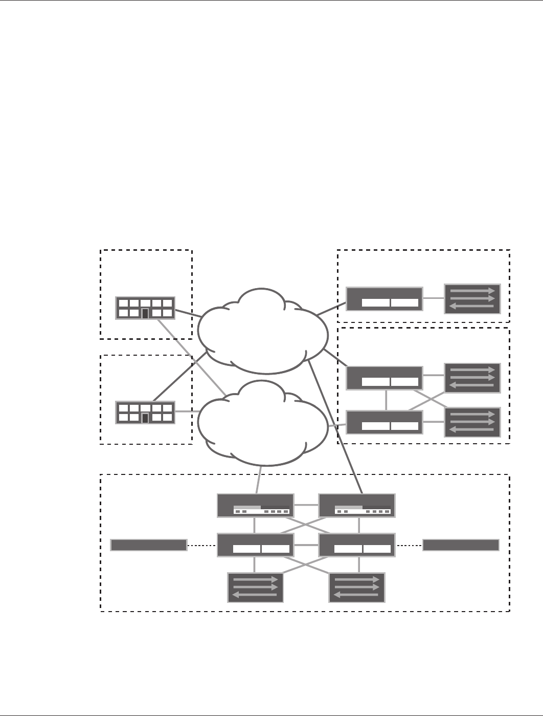
Branch Office Reference Architecture—A High-Level Description
The Juniper Networks
®
Branch Office Reference Architecture categorizes branch office architecture into
three different branch office profiles (see Figure 2). Table 1 summarizes the features the branch office profiles
and the services they provide. This architecture is used as the basis for the discussions and design practice
recommendations. For details concerning the branch office reference architecture, refer to the Branch Office
Reference Architecture paper.
Figure 2: Branch office reference architecture
WAN
INTERNET
DATA CENTER 1
DATA CENTER 2
BRANCH OFFICE
TYPE A
BRANCH OFFICE
TYPE B
BRANCH OFFICE
TYPE C
SSG Series
SSG Series
SSG SeriesSSG Series
J Series
WX Series/WXC SeriesWX Series/WXC Series
J Series
SSG Series
Switch
Switch
Switch
SwitchSwitch