
manual


Table Of Contents
- Introduction
- Scope
- Design Considerations—Connectivity at the Branch Office
- Branch-Office Connectivity over IPsec VPN
- Design Recommendations
- Routing Information Protocol
- Traffic Load Balancing for Type B and Type C Branch Deployments
- Using Border Gateway Protocol for Large Networks
- Using OSPF for Small Number of Branch Offices
- Using Auto Connect VPN to Create Branch-to-Branch IPsec Tunnels
- High Availability for the Branch Office
- High Availability Requirement Levels (Link, Device, Device, and Link Levels)
- High Availability Functionalities
- High Availability for Branch Office Type A
- VPN Security Zone Configuration for Type A
- High Availability for Branch Office Type B
- Using Secure Services Gateway for Type B
- High Availabilty for Branch Office Type C
- Connectivity at the Data Center
- Implementing a High Availability Enterprise Network at the Data Center
- Quality of Service Design Requirements
- WX Design Requirements
- Summary
- Appendix A Related Documents
- Appendix B Naming Conventions
- Appendix C Products
- About Juniper Networks
- Figure 1: Connecting branch offices, campus locations, and data centers over a single converged network
- Figure 2: Branch office reference architecture
- Figure 3: Multi-tiered/layered network architecture
- Figure 4: Two-tier network design for data centers
- Figure 5: Branch with dual internet connections (load balancing using ECMP)
- Figure 6: BGP routing design
- Figure 7: Star topology – connecting branches to central hub
- Figure 8: AC VPN provisioned tunnels between branches in the same region
- Figure 9: Multi-tier topology
- Figure 10: HA configuration for Type A
- Figure 11: VPN security zone configuration for Type A
- Figure 12: Type B optimized – HA configuration
- Figure 13: Type B – security zones
- Figure 14: Type C – HA configuration
- Figure 15: Intra-branch using OSPF
- Figure 16: Branch Type C – security zones
- Figure 17: Enterprise network for the data center
- Figure 18: M Series Multiservice Edge Routers
- Figure 19: Internet firewalls
- Figure 20: VPN firewalls
- Figure 21: VPN firewall IPS policy
- Figure 2: Branch office reference architecture
Copyright © 2010, Juniper Networks, Inc. 25
APPLICATION NOTE - Branch Office Connectivity Guide
from accepting upstream routing information, namely the default route. If the firewall were still in the process of
accepting the default route, then it would take that route and pass it to the shared services core. This would force all
of the traffic through the firewall even though the required VSD is not active on the device.
To accomplish this, interface monitoring is enabled. Interface monitoring states that if the monitored interface
changes to a specific state, then that interface must change to a different state. In this case, if the NOC or out-
of-band interface fails, then both Internet-facing interfaces go down. If both Internet interfaces fail, but the NOC
interface stays up, the VSD must fail over because the VSD must be on the firewall that has access to the default
route being received by the edge routers. To accomplish this, VSD 1 tracks the next-hop IP addresses on the
Internet-facing interfaces. If that IP address is no longer accessible, then the OSPF neighbor relationship will be
down and the link essentially fails. If both Internet interfaces fail, then the firewall will fail over VSD 1.
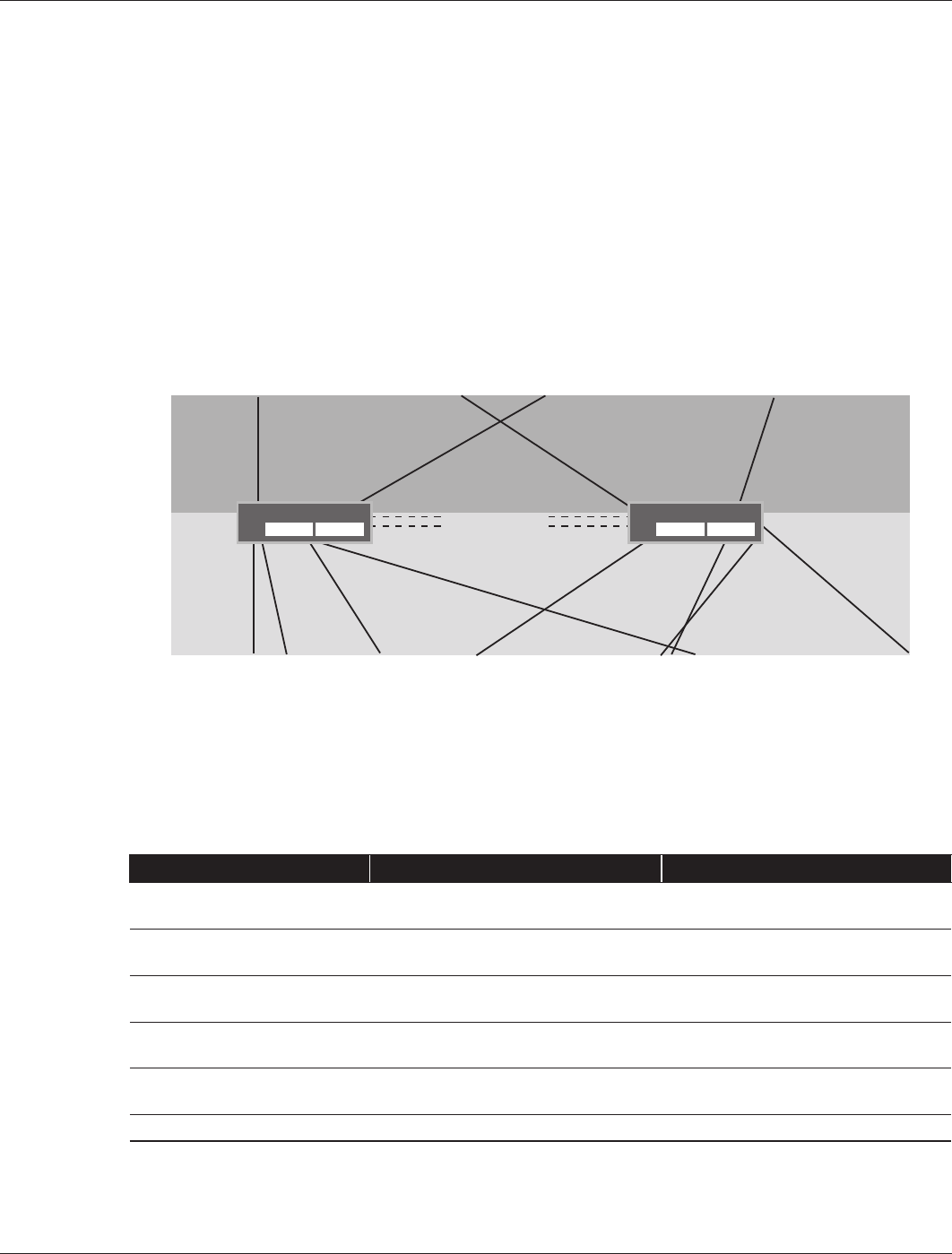
The firewalls are deployed in an NSRP cluster and cross-connect to each other using 10/100 interfaces, as shown
in Figure 19. One interface is dedicated as an out-of-band management port and does not pass any traffic. It is only
used for management purposes. The NOC has only one interface from each firewall and it is not full meshed, so it
also uses a 10/100 interface that operates like a traditional NSRP active/passive interface. Table 5 summarizes the
Internet firewall connectivity and interfaces. For a description of the conventions used for Juniper Networks devices
and links, see Appendix B Naming Conventions.
Figure 19: Internet firewalls
Each of the two firewalls has its own unique IP address on the physical interface. However, both firewalls share
a VSI interface. This VSI is part of VSD 1 and not the typical VSD 0 that is used in an active/passive interface. It is
a passive OSPF interface that allows only the firewall with this interface in an active state to transmit a link-state
advertisement (LSA) for this network. The VSI allows all the hosts in the NOC to use this interface as a default route.
If a device failure occurs, the backup device takes over using the same VSI interface.
Table 5: Internet Firewall Connectivity and Interfaces
Function SSG Series (A) SSG Series (B)
Edge router connectivity
M Series (A)
Gigabit Ethernet ethernet0/0 Gigabit Ethernet ethernet0/1
Edge router-connectivity
M Series (B)
Gigabit Ethernet ethernet0/0 Gigabit Ethernet ethernet0/1
Shared services connectivity
Switch (A)
10/100 ethernet0/2 10/100 ethernet0/3
Shared services connectivity
Switch (B)
10/100 ethernet2/1 10/100 ethernet0/2
Router-router HA interfaces 10/100 ethernet2/2 – HA
10/100 ethernet2/3 – HA
10/100 ethernet2/2 – HA
10/100 ethernet2/3 – HA
Router-router interface Gigabit Ethernet (ge-0/1/3.0) Gigabit Ethernet (ge-0/1/3.0)
Juniper deploys the other four interfaces into two separate networks as a full mesh and all use Gigabit Ethernet
interfaces. Two of the interfaces connect into the Internet routers, and the other two interfaces connect into the
shared services core.
SSG
Series (A)
SSG
Series (B)
ethernet0/0
172.18.8.2/30
OSPF Cost-5
ethernet0/1
172.18.8.14/30
OSPF Cost-1000
ethernet0/0
172.18.8.10/30
OSPF Cost-500
ethernet2/0
192.168.128/24
ethernet0/0
172.18.8.34/30
OSPF Cost- 500
ethernet2/1
192.168.4.3/24
ethernet0/3
172.18.8.83/30
OSPF Cost-1000
ethernet2/0
192.168.3.127/24
ethernet2/1
192.168.4.2/24
ethernet0/2
172.18.8.26/30
OSPF Cost-5
ethernet0/3
172.18.8.30/30
OSPF Cost-10
ethernet0/1
172.18.8.8/30
OSPF Cost-10
loopback.1
172.18.8.43
loopback.1
172.18.8.42
ethernet2/2-HA
ethernet2/3-HA