
manual


Table Of Contents
- Introduction
- Scope
- Design Considerations—Connectivity at the Branch Office
- Branch-Office Connectivity over IPsec VPN
- Design Recommendations
- Routing Information Protocol
- Traffic Load Balancing for Type B and Type C Branch Deployments
- Using Border Gateway Protocol for Large Networks
- Using OSPF for Small Number of Branch Offices
- Using Auto Connect VPN to Create Branch-to-Branch IPsec Tunnels
- High Availability for the Branch Office
- High Availability Requirement Levels (Link, Device, Device, and Link Levels)
- High Availability Functionalities
- High Availability for Branch Office Type A
- VPN Security Zone Configuration for Type A
- High Availability for Branch Office Type B
- Using Secure Services Gateway for Type B
- High Availabilty for Branch Office Type C
- Connectivity at the Data Center
- Implementing a High Availability Enterprise Network at the Data Center
- Quality of Service Design Requirements
- WX Design Requirements
- Summary
- Appendix A Related Documents
- Appendix B Naming Conventions
- Appendix C Products
- About Juniper Networks
- Figure 1: Connecting branch offices, campus locations, and data centers over a single converged network
- Figure 2: Branch office reference architecture
- Figure 3: Multi-tiered/layered network architecture
- Figure 4: Two-tier network design for data centers
- Figure 5: Branch with dual internet connections (load balancing using ECMP)
- Figure 6: BGP routing design
- Figure 7: Star topology – connecting branches to central hub
- Figure 8: AC VPN provisioned tunnels between branches in the same region
- Figure 9: Multi-tier topology
- Figure 10: HA configuration for Type A
- Figure 11: VPN security zone configuration for Type A
- Figure 12: Type B optimized – HA configuration
- Figure 13: Type B – security zones
- Figure 14: Type C – HA configuration
- Figure 15: Intra-branch using OSPF
- Figure 16: Branch Type C – security zones
- Figure 17: Enterprise network for the data center
- Figure 18: M Series Multiservice Edge Routers
- Figure 19: Internet firewalls
- Figure 20: VPN firewalls
- Figure 21: VPN firewall IPS policy
- Figure 2: Branch office reference architecture
22 Copyright © 2010, Juniper Networks, Inc.
APPLICATION NOTE - Branch Office Connectivity Guide
Internet Connections
Because HA is an integral part of the design, the solution uses two provider links. The active/active Internet
connection uses two edge routers, which provides device redundancy and ensures service accessibility. BGP feeds
provide failover protection from each of the providers, allowing the Internet to use the best path to the local network
in the event of failure. Routing information is passed back to the network core using the IGP.
Because the design uses two separate Internet links, you can connect to two completely separate networks. Each
link is diverse and provides a different peering design on the Internet. It is possible to use more than two different
providers—that design decision is left to the discretion of each organization. The more connections provided
potentially increase the availability of the Internet.
Border Gateway Protocol or External Border Gateway Protocol Operation
Each router has one external BGP or EBGP session for connecting directly to the provider. To give the design routing
continuity to the Internet, each of these routers has what is called an “internal BGP session” to each other. Internal
BGP is a session that occurs within one autonomous system, whereas EBGP occurs between two autonomous
systems. This allows the network to determine the best possible path to the remote network.
The goal here is not to perform load sharing, but to provide the most efficient path to the remote network. It is also
possible for a packet to exit one Internet link and then return through the other link because of the remote network’s
routing policy. This routing policy element has been accounted for in this design by controlling return traffic using the
IGP. The active preferred path is symmetrical because of IGP costing.
Failover between the links is an automatic process because of BGP. Once a link is lost, the propagation of the routes
from the core network is lost also. This path is removed from the Internet and the other path routes all traffic.
The default route is generated when a router has an active BGP connection. The route is generated locally as an
aggregate and as a reject route. Because the edge routers have a complete routing table to the Internet, the reject
route drops any traffic that is not destined to an active BGP route. This action preserves bandwidth because if the
route does not exist in BGP, there is no reason to forward the traffic. If the EBGP peering connection is lost, then the
router no longer distributes the default route into the IGP.
The edge routers contain aggregate routes for all of the public IP addresses used on the firewalls. They are sent out
to the edge routes connected through ISP, ensuring that the routes are sent to the Internet through BGP, even in
the event that these routes are not received through OSPF. It would be possible to send them out in the event they
were received through OSPF only. However, it is possible that the routes would flap if they were not received from the
firewalls. Flapping routes to an ISP could cause the routes to be blacklisted on the Internet. The only case where an
administrator would want to send routes, if they were received through OSPF, is if the IP address ranges would be
transported to a different data center or Internet connection location on the network.
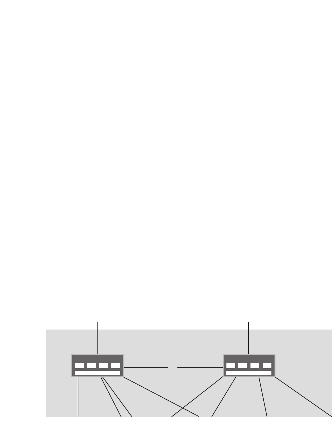
Edge Routers
In this design, two Juniper Networks M Series Multiservice Edge Routers were used. They were selected for two
primary reasons: interface capacity and throughput. As shown in Figure 18, each router uses six total links. Table 4
summarizes the connectivity characteristics of each link for both the A and B edge routers. For a description of the
conventions used for Juniper Networks devices and links, see Appendix B Naming Conventions.
Figure 18: M Series Multiservice Edge Routers
M Series (A) M Series (B)
ge-0/1/0.0
1.253.0.2/30
OSPF-Passive
so-0/1/0.0
1.254.0.2/30
OSPF-Passive
ge-0/1/3.0
172.18.8.5/30
OSPF Cost-1
ge-0/0/0.0
172.18.8.5/30
OSPF-Cost-10
ge-0/0/1.0
172.18.8.13/30
OSPF-Cost-1000
ge-0/0/2.0
172.18.8.21/30
OSPF-Cost10
ge-0/0/3.0
172.18.8.133/30
OSPF-Cost-1000
ge-0/0/0.0
172.18.8.1/30
OSPF Cost-5
ge-0/0/1.0
172.18.8.9/30
OSPF Cost-500
ge-0/0/2.0
172.18.8.18/30
OSPF Cost-5
ge-0/0/3.0
172.18.8.130/30
OSPF Cost-500
ge-0/0/3.0
172.18.8.25/30
OSPF Cost-1
Io0.0
172.18.8.41
Io0.0
172.18.8.40
1
AREA 1 DATA
CENTER A
ISP C ISP B