
manual


Table Of Contents
- Introduction
- Scope
- Design Considerations—Connectivity at the Branch Office
- Branch-Office Connectivity over IPsec VPN
- Design Recommendations
- Routing Information Protocol
- Traffic Load Balancing for Type B and Type C Branch Deployments
- Using Border Gateway Protocol for Large Networks
- Using OSPF for Small Number of Branch Offices
- Using Auto Connect VPN to Create Branch-to-Branch IPsec Tunnels
- High Availability for the Branch Office
- High Availability Requirement Levels (Link, Device, Device, and Link Levels)
- High Availability Functionalities
- High Availability for Branch Office Type A
- VPN Security Zone Configuration for Type A
- High Availability for Branch Office Type B
- Using Secure Services Gateway for Type B
- High Availabilty for Branch Office Type C
- Connectivity at the Data Center
- Implementing a High Availability Enterprise Network at the Data Center
- Quality of Service Design Requirements
- WX Design Requirements
- Summary
- Appendix A Related Documents
- Appendix B Naming Conventions
- Appendix C Products
- About Juniper Networks
- Figure 1: Connecting branch offices, campus locations, and data centers over a single converged network
- Figure 2: Branch office reference architecture
- Figure 3: Multi-tiered/layered network architecture
- Figure 4: Two-tier network design for data centers
- Figure 5: Branch with dual internet connections (load balancing using ECMP)
- Figure 6: BGP routing design
- Figure 7: Star topology – connecting branches to central hub
- Figure 8: AC VPN provisioned tunnels between branches in the same region
- Figure 9: Multi-tier topology
- Figure 10: HA configuration for Type A
- Figure 11: VPN security zone configuration for Type A
- Figure 12: Type B optimized – HA configuration
- Figure 13: Type B – security zones
- Figure 14: Type C – HA configuration
- Figure 15: Intra-branch using OSPF
- Figure 16: Branch Type C – security zones
- Figure 17: Enterprise network for the data center
- Figure 18: M Series Multiservice Edge Routers
- Figure 19: Internet firewalls
- Figure 20: VPN firewalls
- Figure 21: VPN firewall IPS policy
- Figure 2: Branch office reference architecture
Copyright © 2010, Juniper Networks, Inc. 17
APPLICATION NOTE - Branch Office Connectivity Guide
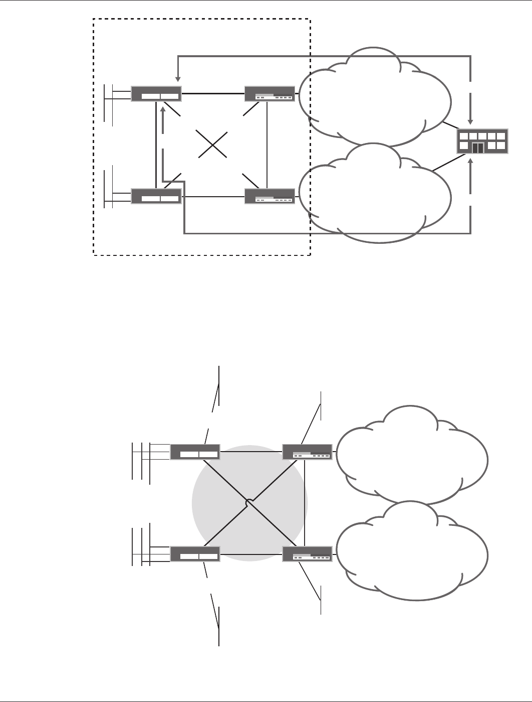
Figure 14: Type C – HA configuration
Branch office Type C uses OSPF to advertise loopback interfaces used to terminate the IPsec tunnels. The NSRP
that is monitoring the interfaces facing the trust and guest zones (as well as the interfaces connecting to the Juniper
Networks J Series Services Routers) determines the status of this loopback interface. The loopback interfaces
terminating the tunnels are the VSIs that are part of Virtual Security Device (VSD) group 1. Whichever device has
this VSI active—SSG Series (A) or SSG Series (B)—propagates the VSI addresses to the J Series routers using OSPF.
Similarly, the J Series (B) router injects a default route into OSPF, while the J Series (A) router injects a route to the
PTP network that also uses OSPF. Figure 15 illustrates this process.
Figure 15: Intra-branch using OSPF
1.2.0.6
172.18.8.162
SSG Series
SSG Series
J Series
J Series
DATA
CENTER A
10.255.1.20 10.255.1.24
10.255.5.20
192.168.10.0/24
1.140.1.0/24
INTERNET
PTP NETWORK
10.255.5.254
10.255.1.254
e0/9:1
e0/1:1
e0/9:1
e0/1:1
172.18.140.6
e0/0
172.18.140.13
ge-0/0/2
172.18.140.2
e0/0
172.18.140.1
172.18.140.13
ge-0/0/2
172.18.140.10
e0/2
172.18.140.9
ge-0/0/2
172.18.140.14
e0/2
loopback 1:1 172.18.1.3/32
loopback 2:1 1.4.17.24/32
loopback 1:1 172.18.1.3/32 (normally inactive)
loopback 2:1 1.4.17.24/32 (normally inactive)
BRANCH OFFICE
SSG Series
SSG Series
J Series
J Series
10.140.0.1/24
1.140.1.0/24
192.168.10.0/24
INTERNET
PTP NETWORK
e0/9:1
e0/8:1
e0/9:1
e0/8:1
e0/1:1
e0/1:1
loopback 1:1 172.18.1.3/32 (normally inactive)
loopback 2:1 1.4.17.24/32 (normally inactive)
loopback 1:1 172.18.1.3/32
loopback 2:1 1.4.17.24/32
OSPF
AREA 0
Injects address of
loopback.1:1 and
loopback.2:2 into
OSPF if VSD 1 is
active on this device
Injects a route to
the PTP network
into OSPF
Injects a default
route into OSPF
Injects address of
loopback.1:1 and
loopback.2:2 into
OSPF if VSD 1 is
active on this device